


PT2500 rev (G) 10/23/96
Installation & Configuration
Your new Harman Kardon receiver is
designed to provide the best reproduction
from both movies and musical programs.
To assure that the unit operates to its
fullest capability, it is important that you
spend a few minutes to properly install
and configure all of the elements in your
new system. Some, or all of the following
steps will apply to your system, depend-
ing on the equipment in use. If you have
any questions concerning the installation
of this product consult your local dealer,
or contact the Harman Kardon web site
at http://www.harmankardon.com.
System Component
Connections
IMPORTANT SAFETY NOTE: Many
products feature automatic turn on cir-
cuitry which may accidentally be activat-
ed when making connections. For your
safety and to prevent damage to speakers,
amplifiers and other components we
strongly recommend that all equipment
power be turned off, or that AC power
cords be unplugged when any system
connections are made or changed.
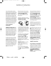
Using high quality interconnect cables,
connect all source components to the
appropriate input jacks on the rear
panel. When connecting audio recorders
and VCRs it is important to make certain
that the PLAY/OUT jacks on the recorders
are connected to the PLAY jacks on the
PT2500, and that the RECORD/IN jacks
of the recorders are connected to the
REC jacks on the PT2500.
7
If the phono input is used, connect the
small ground wire connection furnished
on most turntables to the System
Ground Terminal ™ on the rear
panel. This will greatly reduce system
noise and hum.
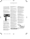
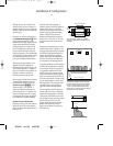
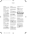
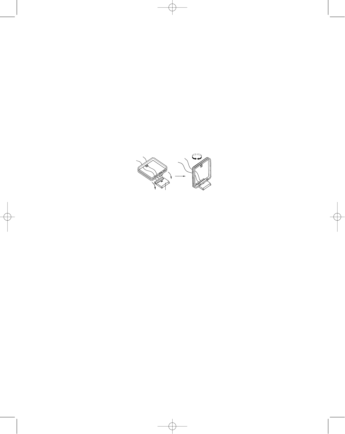
Assemble the supplied AM loop antenna
as shown below and connect it to the AM
ANTENNA Terminals e.
It may be necessary to rotate the antenna
or change its position to achieve the best
AM reception. Connect an FM antenna to
the FM Antenna Terminals. A 300
ohm to 75 ohm adapter may be required
for some antennae.
If a PA5800 or other compatible amplifi-
er will be used, connect the supplied
accessory cable to the Remote
Amplifier Trigger Jack › on the
PT2500. Connect the other end to the
appropriate jack on your amplifier.
Consult the amplifier manual for further
instructions.
IMPORTANT NOTE: Do not connect
amplifier trigger cables to the “IR
Remote Control” jacks on this or any
other equipment.
If you are using the PT2500 to switch
video inputs, connect either MONITOR
output ‹ to a video input on your TV or
projector.
AM LOOP ANTENNA SETTING
Stand and place it on a shelf, or hang it on a wall.
LEG
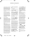
The rear panel accessory outlets on the
PT2500 may be used to power low cur-
rent devices such as CD payers or tape
decks. The SWITCHED Accessory
AC Power Outlets ‡ are activated
only when the PT2500 is turned on. The
UNSWITCHED Accessory AC
Power Outlets fl may be used with
VCRs, as the power to these outlets is live
as long as the PT2500 remains connect-
ed to an AC power source.
CAUTION: The total power load for all
products connected to the accessory out-
lets must not exceed 100 watts. Do not
use them for high current devices such as
power amplifiers.
If the PT2500’s front panel remote sensor
Ò is blocked by cabinet doors you may
still operate the unit via remote control
with the use of an optional external
remote sensor. Connect the output of the
sensor to the rear panel REMOTE
CONTROL Extension Input ·.
This jack may also be used as the IR
input from compatible multiroom con-
trol systems. The sensor may be looped
to other components by connecting the
REMOTE CONTROL Extension
Output ° to the IR remote input jack
of other compatible components.
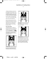
Amplifier Connections
Since the PT2500 is a tuner/preamplifier,
it does not include any on board power
amplifiers. The final step in the installa-
tion process is to connect the unit to the
amplifiers for each channel. Using high
quality audio interconnect cables, con-
nect the FRONT, CENTER and
SURROUND Channel Outputs
cbato the appropriate input jacks
of a power amplifier.
•PT2500(g).qx 10/23/96 7:36 AM Page 8