


REAR PANEL CONNECTIONS 9
ENGLISH
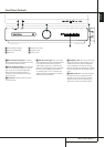
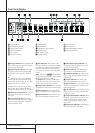
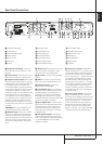
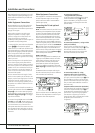
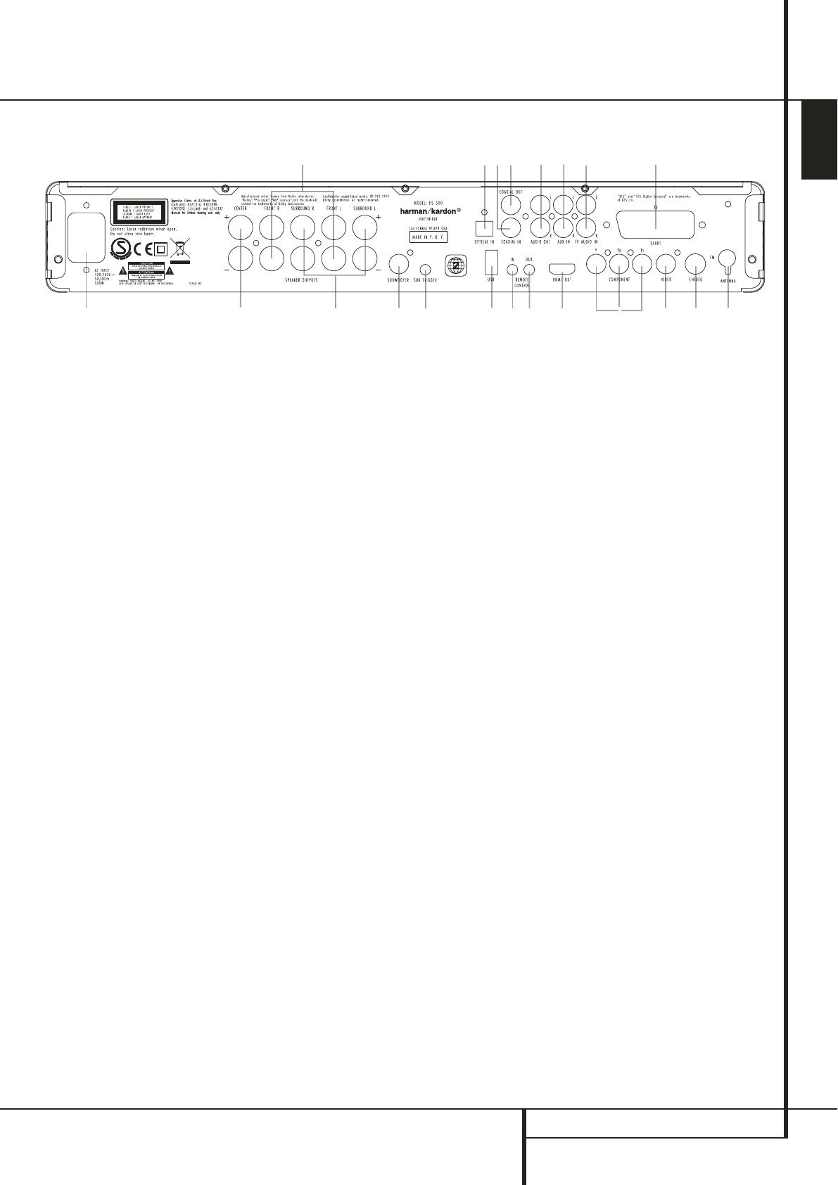
Rear Panel Connections
3
1
0
2
4
5
K
7
E8
A
B
6
F
G
H
I
J
9
D
C
0
Composite Video Output
1
S-Video Output
2
Component Video Outputs
3
Scart TV Output
4
AC Power Cord
5
FM Antenna
6
Audio In
7
Subwoofer Output
8
Coaxial Digital Input
9
Optical Digital Input
A
Analog Audio Outputs
B
Front Speaker Outputs
C
Center Speaker Outputs
D
Surround Speaker Outputs
E
Coaxial Digital Output
F
Subwoofer Trigger Output
G
USB On-The-Go Input
H
HDMI Output
I
Remote IR Output
J
Remote IR Input
K
TV Audio In
0
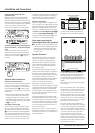
Composite Video Output: Connect this
jack to the video input on a television or video
projector.
1
S-Video Output: Connect this jack to the S-
Video input on a television or video projector.
2
Component Video Outputs: These outputs
carry the component video signals for connection
to display monitors with component video inputs.
For standard analog TV's or projectors with
inputs marked Y/Pr/Pb or Y/Cr/Cb, connect these
outputs to the corresponding inputs. If you have
a high-definition television or projector that is
compatible with high scan rate progressive video,
connect these jacks to the “HD Component”
inputs. Note that if you are using a progressive
scan display device, then ”Progressive” must be
selected in the Video Set-up Menu in order to
take advantage of the progressive scan circuitry.
See page 20 for more information on progressive
scan video.
IMPORTANT:These jacks should NOT be con-
nected to standard composite video inputs.
3
SCART OUT (TV): If your TV has a SCART
socket, you can connect a SCART cable to your
TV and to your DVD Player for improved video
quality. The SCART cable carries both audio and
video.You can select Composite Video or RGB
video for that SCART connector’s video output
signal.
4
AC Power Cord: Connect this plug to an AC
outlet. If the outlet is controlled by a switch,
make certain that it is in the ON position.
5
FM Antenna: Connect to the supplied FM
antenna.
6
Audio In: Connect to a line-level analog
audio source:TV, tape player, Minidisc, PC, etc.
7
Subwoofer Output: Connect to the
SUB/LFE input on the subwoofer.
8
Coaxial Digital Input: Connect the coax
digital output from a DVD player, HDTV receiver,
LD player, MD player, satellite receiver or CD
player to this jack.The signal may be either a
Dolby Digital signal, DTS signal or a standard
PCM digital source. Do not connect the RF digital
output of an LD player to these jacks.
9
Optical Digital Input: Connect the optical
digital output from a DVD player, HDTV receiver,
LD player, MD player, satellite receiver or CD
player to this jack.The signal may be either a
Dolby Digital signal, DTS signal or a standard
PCM digital source.
A
Analog Audio Outputs: Connect these
jacks to the analog audio input on a TV set or
external audio system for analog audio playback
or to the RECORD/INPUT jacks of an audio
recorder for recording.
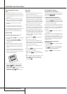
B
Front Speaker Outputs: Connect these
outputs to the matching + or – terminals on your
left and right speakers. In conformance with the
new CEA color code specification, the White ter-
minal is the positive, or "+" terminal that should
be connected to the red (+) terminal on Front
Left speaker with the older color coding, while
the Red terminal is the positive, or "+" terminal
that should be connected to the red (+) terminal
on Front Right speaker. Connect the black (–)
terminals on the HS to the black (–) terminals on
the speakers. See page 15 for more information
on speaker polarity.
C
Center Speaker Outputs: Connect these
outputs to the matching + and – terminals on
your center channel speaker. In conformance with
the new CEA color code specification, the Green
Terminal is the positive, or "+" terminal that
should be connected to the red (+) terminal on
speakers with the older color coding. Connect
the black (–) terminal on the HS to the black
negative (–) terminal on your speaker. (See page
15 for more information on speaker polarity.)