


9
9
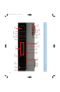
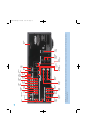
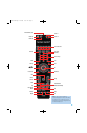
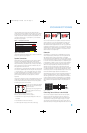
REAR-PANEL CONNECTIONS
AM and FM Antenna Terminals: Connect the included AM and
FM antennas to their respective terminals for radio reception.
Video 1, Video 2 and Video 3 Audio/Video Inputs: These
jacks may be used to connect your video-capable source components
(e.g., VCR, DVD player, cable TV box) to the receiver.
NOTE: The Video 3 source has inputs on both the front and
rear panels of the HK 3490, and you may connect different
devices to each set of inputs. To select between the two sets
of inputs, press the Video 3 Source Selector repeatedly.
Video 1 Audio/Video Outputs: These jacks may be used to
connect your VCR or another recorder.
Video Monitor Output: If some of your sources use video
connections, connect the Video Monitor Output to the corresponding
input on your television or video display to view the sources. No video
signal will be available when an audio-only source input, such as CD
or Tape, is selected.
Remote Infrared (IR) Input and Output: When the remote
IR receiver on the front panel is blocked, such as when the HK 3490
is placed inside a cabinet, connect an optional IR receiver to the Remote
IR Input jack for use with the remote control. The Remote IR Output may
be connected to the Remote IR Input of a compatible source device
(or other product) to enable remote control through the HK 3490. When
several source devices are used, connect them in “daisy chain” fashion.
Update Port: This connection is for authorized service personnel only.
It is used with a proprietary device in the event that a software update
for the HK 3490 becomes available in the future. Do not make any
connections to it.
Reset Button: In the event that the HK 3490 operates erratically, a
system reset may restore proper functionality. Place the unit in Standby
mode by pressing the Power Switch so that the Power Indicator turns
amber. Then use a fine-point pen or other similar object to press the
Reset Button.
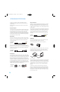
The Bridge/DMP Input: Connect the optional Harman Kardon
or docking station to this input for use with
your iPod, iPod touch or iPhone (not included). Make sure the receiver
is turned off (in Standby mode) when connecting The Bridge or
The Bridge II docking station.
XM Antenna Jack: Plug in an XM antenna module here. The XM
antenna module is purchased separately, and should specify that it is for
home use with an XM Ready product. You will need to subscribe to the
XM service, which is available separately, and activate the service for
your antenna module. (XM service is not available in Alaska and Hawaii.)
Coaxial and Optical Digital Audio Inputs: If a source has a
compatible digital audio output, connect it to one of these jacks for
improved audio performance. Use only one type of digital audio
connection for each source.
AC Power Cord: After you have made all other connections, plug
the AC power cord into an unswitched outlet.
Switched AC Accessory Outlets: You may plug the AC power
cord of one source device into each of these outlets, and it will turn on
whenever you turn on the receiver. Do not use sources that consume
more than 100 watts of power per outlet.
Speaker 1 and 2 Outputs: Use two-conductor speaker wire to
connect each set of terminals to the correct speaker. Observe the
correct polarity (positive and negative connections). Always connect the
positive lead to the red or white terminal on the receiver and the red
terminal on the speaker. Connect the negative lead to the black terminal
on both the receiver and the speaker. Use the Speaker 1/2 Selectors
on the front panel or remote to select either or both pairs of speakers
for playback.
Subwoofer Outputs: If you have a powered subwoofer, connect
these jacks to the line-level inputs on the subwoofer. The same full-
range signal is output through both jacks. Thus, you have the option
of connecting each jack to the line-level input on a separate subwoofer
or to use the full-range outputs to feed a remote room in a distributed-
audio application. If you have only one subwoofer with a single line-level
input, connect it to the right Subwoofer Output on the HK 3490.
Subwoofer Trigger Outputs: Connect these outputs to a
compatible trigger input on the subwoofer connected to the Subwoofer
Output immediately to the right of the Trigger Output. Consult the
owner’s manual for the subwoofer to set its trigger input correctly, and
the subwoofer will automatically turn on or off when the HK 3490 is
turned on or off. In addition, the Trigger Outputs are used with the
Subwoofer Link Switches to conserve energy by powering off the
subwoofer’s amplifier when it is not needed. The Subwoofer Trigger
Outputs send a signal of 15 volts DC.
Subwoofer Link Switches: Each switch affects the subwoofer
connected to the jack immediately to the left of the switch. To use the
switch, first connect the corresponding Subwoofer Trigger Output to
a compatible trigger input on the subwoofer, and make sure the
subwoofer’s instructions are followed to activate its trigger input. When the
Link Switch is on, the HK 3490 will remove the trigger signal whenever
the corresponding pair of main speakers is not in use, thereby conserving
energy that would otherwise be used to maintain the subwoofer’s amplifier
in Standby mode. This feature is activated any time no signal is present at
the main speaker outputs, including when the Speaker 1/2 Switch turns
off both speaker pairs, when the HK 3490’s output is muted, or when the
headphones are plugged in. See Table A2 in the appendix for details.
Main-Amp Inputs and Preamp Outputs: These jacks are
normally connected directly to each other with an included jumper.
Some devices, such as equalizers and some loudspeaker systems,
require connection between the Preamp Outputs and Main-Amp
Inputs, in which case the jumpers should be removed and stored in a
safe place for future use. You may also remove the jumpers if you wish
to connect the Preamp Outputs to an external amplifier, or if you wish
to connect another device’s line-level output directly to the HK 3490’s
power amplifier for a special application.
Tape Outputs: These jacks may be used to connect your CDR or
another audio-only recorder.
HKP1696-3490.qxd 4/22/08 3:37 PM Page 9