


REAR-PANEL CONNECTIONS
10 REAR-PANEL CONNECTIONS
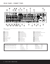
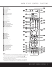
d Switched AC Outlet: These outlets may be used
to power any device you wish to have turned on when
the DPR 1005 is turned on with the
Standby/On
Switch
1.
NOTE: The total power consumption of all devices
connected to the rear panel AC outlets should not
exceed 100 watts.
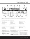
e Front Speaker Outputs: Connect these outputs
to the matching + or – terminals on your left and right
speakers. When making speaker connections always
make certain to maintain correct polarity by connecting
the color-coded (white for front left and red for front
right) (+) terminals on the DPR 1005 to the red (+)
terminals on the speakers and the black (–) terminals
on the DPR 1005 to the black (–) terminals on the
speakers. See page 16 for more information on
speaker polarity.
f Surround Speaker Outputs: Connect these out-
puts to the matching + and – terminals on your sur-
round channel speakers. In conformance with the CEA
color-code specification, the blue terminal is the posi-
tive, or “+” terminal that should be connected to the
red (+) terminal on the Surround Left speaker with
older color-coding, while the gray terminal should be
connected to the red (+) terminal on the Surround
Right speaker with the older color-coding. Connect the
black (–) terminal on the DPR to the matching black
negative (–) terminals for each surround speaker. (See
page 16 for more information on speaker polarity.)
g Surround Back/Multiroom Speaker Outputs:
These speaker terminals are normally used to power
the surround back left/surround back right speakers
in a 7.1 channel system. However, they may also be
used to power the speakers in a second zone, which
will receive the output selected for a multiroom system.
To change the output fed to these terminals from
the default of the Surround Back speakers to the
Multiroom Output, you must change a setting in the
MULTI-ROOM SETUP menu of the OSD
system. See page 39 for more information on config-
uring this speaker output. In normal surround system
use, the brown and black terminals are the surround
back left channel positive (+) and negative (–) con-
nections and the tan and black terminals are the sur-
round back right positive (+) and negative (–) termi-
nals. For multiroom use, connect the brown and black
SBL terminals to the red and black connections on
the left remote zone speaker and connect the tan and
black SBR terminals to the red and black terminals on
the right remote zone speaker.
h Center Speaker Outputs: Connect these outputs
to the matching + and – terminals on your center
channel speaker. In conformance with the CEA color-
code specification, the green terminal is the positive,
or “+” terminal that should be connected to the red
(+) terminal on speakers with the older color-coding.
Connect the black (–) terminal on the DPR to the
black negative (–) terminal on your speaker. (See
page 16 for more information on speaker polarity.)
i Component Video 1 Inputs: These inputs may
be used with any video source device equipped with
analog Y/Pr/Pb or RGB component video outputs. The
factory default is for these jacks to be linked to the
DVD input, but you may change the setting at any
time through the
IN/OUT SETUP menu. See
page 21 for more information on configuring the
component video inputs.
j Component Video 2 Inputs: These inputs may
be used with any video source device equipped with
analog Y/Pr/Pb or RGB component video outputs. The
factory default is for these jacks to be linked to the
Video 2 input, but you may change the setting at any
time through the
IN/OUT SETUP menu. See
page 21 for more information on configuring the com-
ponent video inputs.
k Component Video Monitor Outputs: Connect
these outputs to the component video inputs of a
video projector or monitor. When a source connected
to one of the
Component Video Inputs ij is
selected the signal will be sent to these jacks.
Multiroom IR Input: Connect the output of an IR
sensor in a remote room to this jack to operate the
DPR 1005’s multiroom control system.
Remote IR Input: If the DPR 1005’s front-
panel IR sensor is blocked due to cabinet doors or
other obstructions, an external IR sensor may be
used. Connect the output of the sensor to this jack.
Remote IR Output: This connection permits the
IR sensor in the receiver to serve other remote con-
trolled devices. Connect this jack to the “IR IN” jack on
Harman Kardon (or other compatible) equipment.
A-BUS Connector:
Connect this jack to an optional
A-BUS
®
-certified remote room keypad or amplifier to
extend the multiroom capabilities of your DPR 1005.
See page 39 for more information on A-BUS.
FM Antenna: Connect the supplied indoor or an
optional external FM antenna to this terminal.
AM Antenna: Connect the AM loop antenna sup-
plied with the receiver to these terminals. If an external
AM antenna is used, make connections to the
AM and
GND terminals in accordance with the instructions
supplied with the antenna.
36
35
34
33
32
31