


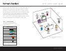
SPEAKER AND DVD CONNECTIONS
A
M Antenna
FM Antenna
240240
91329
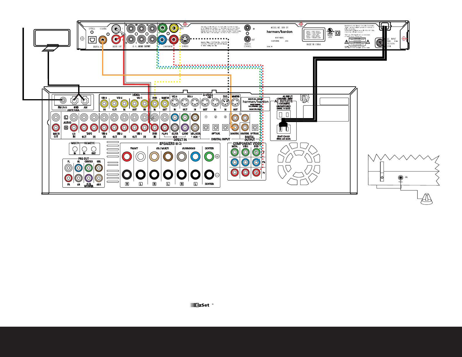
Step 4. Connect AM and FM antennas, as shown above (see page 14).
Step 5. Connect the DVD 31 to the AVR 335 as shown above:
AUDIO connections: Connect the L/R Audio Out jacks on the DVD
to the L/R DVD Audio in jacks on the AVR.
DIGITAL AUDIO connections: Use the enclosed coaxial interconnect
(
orange connectors) to connect the Coaxial Digital Output on the
DVD to the Coaxial Digital 1 Input on the AVR.
VIDEO connections: Depending on the input available on your TV,
use either composite video (
dotted yellow), S-video (dotted black)
or component video (dotted red/blue/green) connections. Only one
connection type is needed.
POWER: Plug the DVD’s AC power cord into the SWITCHED output
on the back of the AVR. Press the Main Power Switch on the DVD so
that it is ON (see page 17).
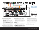
Step 6.
Connect other source devices such as a
VCR,
Cable or Satellite set-
top box,
HDTV receiver or audio recorder using the connections
shown in the Device Connection Options chart and Figure 6 on the
back of this Guide. Plug all sources into an AC power outlet.
Step 7. Connect the AVR to your TV or video display. You must make a
composite, “S” or component video connection corresponding
corresponding to each video source device used in your system.
Remember to switch the TV to the correct input for each source.
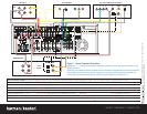
NOTE: The AVR’s on-screen menus are not available when viewing
a component video connection. For that reason, a composite or
S-video connection is recommended, though not required, when
component video is used.
Basic Configuration
Step 8. Select digital inputs: Use the On-Screen Input Setup menu or the
front-panel Digital Select button and the arrow buttons to select an
optical or coaxial digital input, for any digital source of the DVD
(see page 18).
Step 9.
Use
to configure and optimize your system.
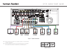
Plug the EzSet+ microphone into the front-panel Headphones
Jack (Fig
.
5).
Place the microphone at the center of the room, or
at your normal listening position. If desired, the mike may be
attached to a standard camera tripod using the threads on the
bottom of the mike. Follow the instructions on pages 20–21 of
the Owner’s Manual, which contains the steps needed to activate
the system. As EzSet+ senses the output of each speaker, you will
hear loud test signals. This is a normal part of the EzSet+ process.
When the on-screen menu indicates that setup is complete, your
system is adjusted for output levels, delay times and speaker set-
tings. Unplug the microphone and store it for future use.
Step 10.
If you are using a component video connection to a digital television,
set the DVD 31’s output to Progressive Scan, as shown on page 17
of the DVD 31 manual.
Step 11.
Your system is configured – sit back and enjoy!
/EQ
/EQ
+
Figure 4 – DVD Connections
Dashed lines (––––) indicate coax
and optical digital audio connections.
Choose either type (but not both) for
each digital audio source.
Figure 5 – Connecting EzSet+
Microphone