


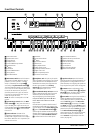


6 FRONT PANEL CONTROLS
Front Panel Controls
9
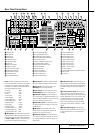
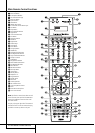
Surround Mode Selector: Press this
button to cycle through the individual surround
modes available after the Surround Mode
Group Selector
5
was pressed (see item
5
above). Note that depending on the type of
input, some modes are not always available. (See
page 32 for more information about surround
modes).
)
Tuning Selector: Press the left side of the
button to tune lower frequency stations and the
right side of the button to tune higher frequency
stations. When a station with a strong signal is
reached,
MANUALTUNED or AUTO
TUNED
will appear in the Main Information
Display
˜
(see page 40 for more information
on tuning stations).
!
Tuner Band Selector: Pressing this button
will automatically switch the AVR to the Tuner
mode. Pressing it again will switch between the
AM and FM frequency bands, holding it pressed
for some seconds will switch between stereo and
mono receiving and between automatic and
manual tuning mode (See page 40 for more
information on the tuner).
@
Set Button: When making choices during
the setup and configuration process, press this
button to enter the desired setting as shown in
the Main Information Display
˜
into the
AVR’s memory.
#
Preset Stations Selector: Press this
button to scroll up or down through the list of
stations that have been entered into the preset
memory. (See page 40 for more information on
tuner programming.)
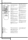
$
›
Button: When an adjustment is being
made using the Channel Select
Ù
or Digital
Select
Û
buttons, this button may be pressed
to scroll through the available options.
%
Input Source Selector: Press this button to
change the input by scrolling through the list of
input sources.
^ RDS Select Button: Press this button to dis-
play the various messages that are part of the RDS
data system of the AVR’s tuner. (See page 40 for
more information on RDS).
& Delay Adjust Selector: Press this button to
begin the process of adjusting the delay settings
for Dolby surround modes. See page 26 for more
information on delay adjustments.
*
Digital Optical 3 Input: Connect the optical
digital audio output of an audio or video product
to this jack.When the Input is not in use, be
certain to keep the plastic cap installed to avoid
dust contamination that might degrade future
performance.
(
Input/Output Status Indicators: These
LED indicators will normally light green to show
that the front panel Video 4 A/V
Ô
jacks or the
Coaxial 3 digital
Ó
jack is operating as an
input.When either of these jacks has been con-
figured for use as an output, the indicator will
turn red to show that the jack may be used for
recording. (See page 21 for more information on
configuring the front panel jacks as outputs,
rather than inputs.)
Ó
Digital Coax 3 Jack: This jack is normally
used for connection to the output of portable
audio devices, video game consoles or other
products that have a coax digital jack. It may
also be configured as an output jack, to feed a
digital signal to a CD-R, MiniDisc or other digital
recording device. (See page 21 for information
on configuring the Digital Coax 3 Jack to an
output.)
Ô
Video 4 Input/Output Jacks: These
audio/video jacks may be used for temporary
connection to video games or portable audio/
video products such as camcorders and portable
audio players. They may also be configured as
output jacks (also S-Video) to feed a signal to
any recording Audio or Video device (see page 35
for more information).
Front-Panel Control Door: To open the
door so that the front-panel jacks and controls
behind this door may be accessed, gently pull the
door down and towards you using either upper
corner of the door.
Ò
Surround Mode Indicators: The current
selected mode or function will appear as one of
these indicators. Note that when the unit is
turned on, the entire list of available modes will
light briefly, and then revert to normal operation
with only the active mode indicator illuminated.
Ú
Speaker/Channel Input Indicators: These
indicators are multipurpose, indicating either the
speaker type selected for each channel or the
incoming data-signal configuration.The left, center,
right, right surround and left surround speaker
indicators are composed of three boxes, while the
subwoofer is a single box.The center box lights
when a “Small” speaker is selected, and the two
outer boxes light when “Large” speakers are
selected.When none of the boxes are lit for the
center, surround or subwoofer channels, no speaker
has been selected for that position. (See page 22
for more information on configuring speakers.) The
letters inside each of the center boxes display
active input channels. For standard analog inputs,
only the L and R will light, indicating a stereo
input.When a digital source is playing, the indica-
tors will light to display the channels begin
received at the digital input.When the letters
flash, the digital input has been interrupted. (See
page 34 for more information on the Channel
Indicators).
Û
Digital Select Button: When playing a
source that has a digital output, press this button
to select between the Optical
* W
and
Coaxial
Ó X
Digital inputs (See page
33 for more information).
Ù
Channel Select Button: Press this button
to begin the process of trimming the channel
output levels using an external audio source.
(For more information on output level trim
adjustment, see page 36).
ı
Volume Control: Turn this knob clockwise
to increase the volume, counterclockwise to
decrease the volume. If the AVR is muted,
adjusting volume control will automatically
release the unit from the silenced condition.
ˆ
Input indicators: The current selected
mode or function will appear as one of these
indicators. Note that when the unit is turned on,
the entire list of available modes will light briefly,
and then revert to normal operation with only
the active mode indicator illuminated.
˜
Main Information Display: This display
delivers messages and status indications to help
you operate the receiver.
¯
Remote Sensor Window: The sensor
behind this window receives infrared signals from
the remote control.Aim the remote at this area
and do not block or cover it unless an external
remote sensor is installed.