


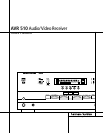
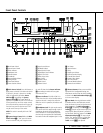
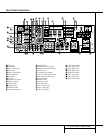
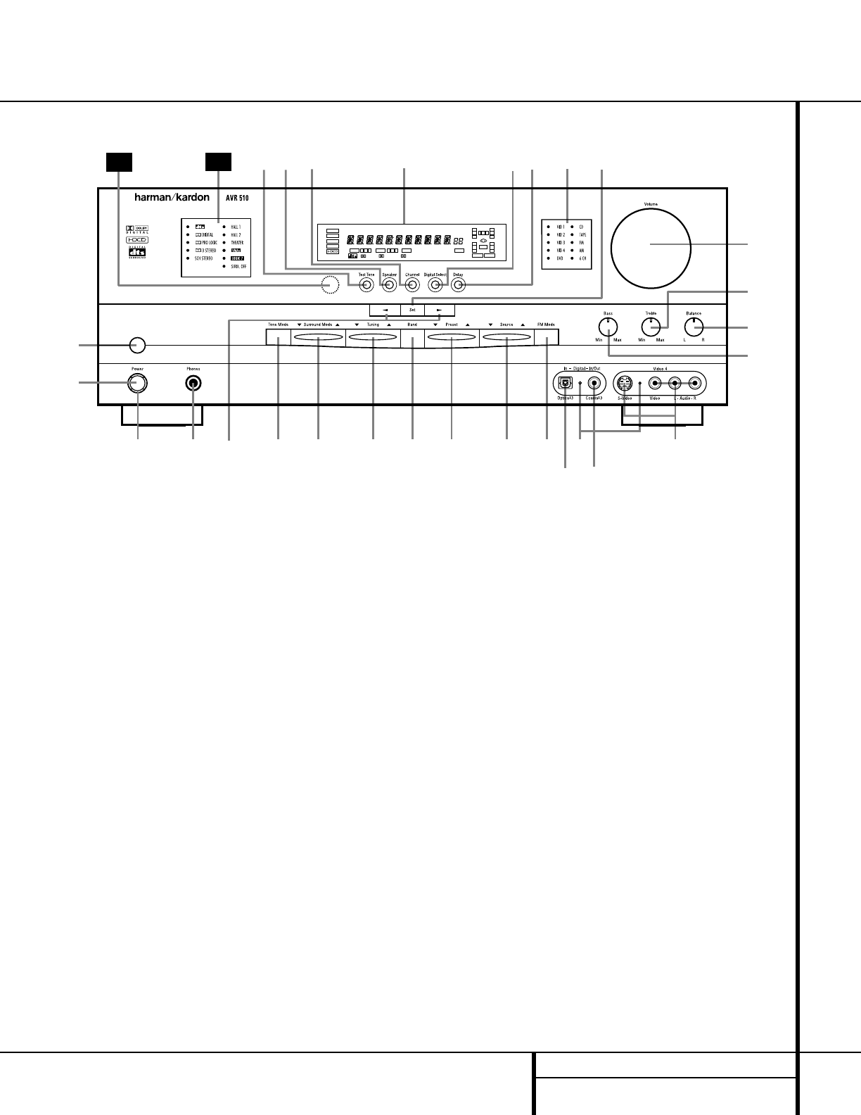
5 FRONT PANEL CONTROLS
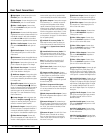
1 Main Power Switch: Press this button to
apply power to the AVR 510. When the switch
is pressed in, the unit is placed in a Standby
mode, as indicated by the amber
Power
Indicator
3 surrounding the System
Power Control
2. This button MUST be
pressed in to operate the unit. To turn the unit
off and prevent the use of the remote control,
this switch should be pressed until it pops out
from the front panel so that the word “OFF”
may be read at the top of the switch.
NOTE: This switch is normally left in the “ON”
position.
2 System Power Control: When the Main
Power Switch
1
is “ON,” press this button
to turn on the AVR 510; press it again to turn
the unit off. Note that the Power Indicator
3
surrounding the switch will turn green
when the unit is on.
3 Power Indicator: This LED will be lit in
amber when the unit is in the Standby mode to
signal that the unit is ready to be turned on.
When the unit is in operation, the indicator will
turn green.
4 Headphone Jack: This jack may be used to
listen to the AVR 510’s output through a pair of
headphones. Be certain that the headphones
have a standard
1
/4" stereo phone plug. Note
that the main room speakers will automatically
be turned off when the headphone jack is in use.
5 Selector Buttons: When you are establish-
ing the AVR 510’s configuration settings, use
these buttons to select from the choices available,
as shown in the
Main Information Display Û
or the on-screen displays.
6 Tone Mode: Pressing this button enables
or disables the Bass and Treble tone controls.
When the button is pressed so that the words
TONE IN appear in the
Main Information
Display
Û, the settings of the Bass & and
Treble ( controls may be used to adjust the
output signals. When the button is pressed so
that the words TONE OUT appear in the
Main
Information Display
Û, the output signal
will be “flat,” without any bass or treble alter-
ation, no matter how the actual
Bass and
Treble controls &( are adjusted.
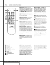
Front Panel Controls
1 Main Power Switch
2 System Power Control
3 Power Indicator
4 Headphone Jack
5 Selector Buttons
6 Tone Mode
7 Surround Mode Selector
8 Tuning Selector
9 Tuner Band Selector
) Preset Stations Selector
! Input Source Selector
@ FM Mode Selector
# Digital Optical 3 Input
$ Input/Output Status Indicator
% Digital Coax 3 Jack
^ Video 4 Input Jacks
& Bass Control
* Balance Control
( Treble Control
Ó Volume Control
Ô Set Button
Input Indicators
Ò Delay
Ú Digital Input Selector
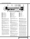
Û Main Information Display
Ù Channel Select Button
ı Speaker Select Button
ˆ Test Tone Selector
˜ Surround Mode Indicators
¯ Remote Sensor Window
Ò
Ú
&
Ô
Ò
Ú
ıÙ
&
Ô
Ò
Ú
ˆ
*
&
(
Ó
Ô
333
111
444
555
666
777
888
999
)))
!!!
@@@
###
%%%
29
30
ÛÛÛ
$
^^^
222
COAXIAL
THEATER
5 CH STEREO
HALL 12
3
-
STEREO
PRO LOGIC
DIGITAL
NIGHT
MULTI
OPTICAL
ANALOG
OSD
LFE
0
CL
0
1 2 3
1 2 3
MEMORY PRESET
SLEEP
AUTO
5.1 LOGIC 7 CM
VMAx NF
MUTE
TUNED ST
O
O
R
O
O
LS
O
O
RS
O
O
DTS
DOLBY D
PCM
MP3