


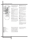

10 REAR PANEL CONNECTIONS
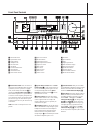
Rear Panel Connections
C
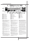
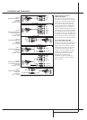
Video Monitor Outputs: Connect these
jacks to the composite and/or S-Video input of a
TV monitor or video projector to view the on-
screen menus and the output of any video source
selected by the receiver’s video switcher.
D
Amplifier Inputs: When the jumper pins
that link the Preamp Outputs
A
with these
inputs are removed, these jacks may be used to
connect any external 5.1 channel source (or 2
channel source, if only Main Inputs are used),
e.g. processors, to the internal amplifiers. (See
page 18 for more information on using these
connections.)
E
Speaker Outputs: Connect these outputs
to the matching + or – terminals on your speak-
ers. When making speaker connections always
make certain to maintain correct polarity by con-
necting the red (+) terminals on the AVR5000 to
the red (+) terminals on the speakers and the
black (–) terminals on the AVR5000 to the black
(–) terminals on the speakers. See page 15 for
more information on speaker polarity.
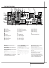
F
Switched AC Accessory Outlet: This out-
let may be used to power any device that you
wish to have turn on when the unit is turned on
with the System Power Control switch
2
.
G
Unswitched AC Accessory Outlet: This
outlet may be used to power any AC device. The
power will remain on at this outlet regardless of
whether the AVR5000 is on or off (in Standby),
provided that the Main Power switch
1
is on.
Note: The total power consumption of all
devices connected to the accessory outlets
should not exceed 100 watts from the
Unswitched Outlet
G
and 50 W from the
Switched Outlet
F
.
H
AC Power Cord: Connect the AC plug to an
unswitched AC wall output.
I
Remote IR Output: This connection per-
mits the IR sensor in the receiver to serve other
remote controlled devices. Connect this jack to
the “IR IN” jack on Harman Kardon or other
compatible equipment.
J
Remote IR Input: If the AVR5000’s front-
panel IR sensor is blocked due to cabinet doors
or other obstructions, an external IR sensor
may be used. Connect the output of the sensor
to this jack.
K
Multiroom IR Input: Connect the output of
an IR sensor in a remote room to this jack to
operate the AVR5000’s multiroom control system.
L
DVD Video Inputs: Connect these jacks to
the composite or S-Video output jacks on a DVD
player or other video source.
M
Video 1 Video Outputs: Connect these
jacks to the RECORD/INPUT composite or
S-Video jack on a VCR.
N
Video 3 Video Inputs: Connect these jacks
to the PLAY/OUT composite or S-Video jacks on
any video source.
O
Video 2 Video Inputs: Connect these jacks
to the PLAY/OUT composite or S-Video jacks on
a second VCR or other video source.
P
Video 2 Video Outputs: Connect these
jacks to the RECORD/INPUT composite or
S-Video jacks on a second VCR.
Q
Video 1 Video Inputs: Connect these jacks
to the PLAY/OUT composite or S-Video jacks on
a VCR or other video source.
R
Optical Digital Inputs: Connect the optical
digital output from a DVD player, HDTV receiver,
LD player,MD player or CD player to these jacks.
The signal may be either a Dolby Digital signal, a
DTS signal or a standard PCM digital source.
S
Coaxial Digital Inputs: Connect the coax
digital output from a DVD player, HDTV receiver,
LD player, MD player or CD player to these jacks.
The signal may be either a Dolby Digital signal,
DTS signal or a standard PCM digital source. Do
not connect the RF digital output of an LD play-
er to these jacks.
T
Digital Audio Outputs: Connect these
jacks to the matching digital input connector on
a digital recorder such as a CD-R or MiniDisc
recorder.
U
Video 3 Audio Inputs: Connect these jacks
to the PLAY/OUT audio jacks on any audio or
video source.
V
Video 2 Audio Inputs: Connect these jacks
to the PLAY/OUT audio jacks on a VCR or other
video source.
W
Video 2 Audio Outputs: Connect these
jacks to the RECORD/INPUT audio jacks on a
VCR or any Audio recorder.
Note: Either the Video or S-Video output of any
S-Video source must be connected to the
AVR5000, not both in parallel, otherwise the
video may be disturbed or its performance be
adversely effected.
X
Component Monitor Outputs: Connect
these outputs to the component video inputs of
a video projector or monitor.When a source
connected to one of the two Component
Video Inputs
YZ
is selected the signal will
be sent to these jacks.
Y
Video 2 Component Video Inputs:
Connect the Y/Pr/Pb component video outputs of
a set top converter box or other video source to
these jacks.
Z
DVD Component Video Inputs: Connect
the Y/Pr/Pb component video outputs of a DVD
player to these jacks.
Note: All component inputs/outputs can be
used for RGB signals too, in the same way as
described for the Y/Pr/Pb signals, then connected
to the jacks with the corresponding color.
RGB connection is not possible if the source
outputs a separate sync signal.