


25
INSTALLATION
STEP NINE – Install a Multizone System
The AVR 3600 offers several methods of distributing audio to
other areas in your home.
IMPORTANT SAFETY NOTE: Installing a multizone
system typically requires running cables inside walls. Always
comply with the appropriate safety codes when installing con-
cealed wiring, particularly all applicable state and local build-
ing codes and the NEC (National Electrical Code). Failure to do
so may present a safety hazard. If you have any doubt about
your ability to work with electrical and telecommunications
wiring, hire a licensed electrician or custom installer to install
the multizone system.
When the system is installed using methods B or C below, multizone
operation takes over the Surround Back/Zone 2 amplifier channels,
limiting the system in the main listening room to 5.1 channels.
Select one or all of these methods for audio
distribution:
A. Connect an external amplifier to the Zone 2
Audio Outputs. It is recommended that you place the amplifier
in the same room as the AVR 3600 so that a shorter length of inter-
connect cable is used with a long run of speaker wire to the remote
room. A long run of interconnect cable would be subject to signal
degradation. Depending on your amplifier, distribute the audio sig-
nal to a single pair of speakers, or to several pairs placed in differ-
ent rooms.
The Zone 2 Audio Outputs offer the benefit of 7.1-channel audio in
the main room simultaneously with multizone operation. However,
the benefit is achieved with the expense of an additional compo-
nent, i.e., the amplifier.
B. Connect the remote room’s speakers directly
to the Surround Back/Zone 2 Speaker Outputs.
Reassign the Surround Back amplifier channels to power the
speakers (see page 47).
Your main system will be limited to 5.1 channels, affecting playback
of programs recorded in 6.1 or 7.1 channels.
C. Connect an external amplifier to the Surround
Back/Zone 2 Preamp Outputs. This method requires an
additional amplifier, but may increase the total number of remote
rooms when used with methods A and B.
D. Connect an A-BUS hub or other A-BUS com-
ponents to the A-BUS port. Use Category 5/5e cable,
as described in the instructions for your A-BUS components. The
A-BUS system carries the audio signal to the remote components,
while receiving IR control codes. A hub may distribute audio to
many remote rooms. To control source devices exclusively from the
remote A-BUS module, connect the AVR’s A-BUS IR Output to a
compatible IR input on the source. This avoids having conflicting
control commands sent to a source intended for the A-BUS system.
IR commands received from the A-BUS system are also
distributed to the AVR’s other IR outputs. Visit the Web site
at www.harmankardon.com for information on available
Harman Kardon hubs, the ABH 4 and ABH 4000, and amplified
in-wall modules, the AB 1 and AB 2.
Connect IR Control Devices to the Zone 2
IR Input
For methods A, B and C, connect an IR control device to the Zone 2
IR Input for remote-room control of the multizone system, source
devices and volume in the remote zone. An A-BUS system does
not require a separate IR control connection.
NOTE: Only analog audio sources are available to the multi-
zone system. For digital sources, make a second, analog audio
connection. The Bridge III source is available to the multizone
system.
STEP TEN – Plug in AC Power Cords
Before plugging the AVR into an unswitched electrical outlet, make
sure the Main Power Switch on the rear-panel is off, to prevent the
possibility of damaging the AVR in case of a transient power surge.
You may plug one device that draws no more than 50 watts into
the AC Switched Accessory Outlet on the rear panel. Turn on the
device’s mechanical or master power switch, and that device will
power on any time the AVR 3600 is turned on (some devices may
require additional steps to power on from their standby mode). If the
device has a clock or must always be on (such as a cable set-top
box programmed to make recordings), do not plug it into this outlet.
The AVR 3600 is equipped with a detachable power cord, allowing
you to fully wire your system before installing the AVR. Plug the
male end of the cord into an unswitched AC outlet, and the female
end into the AVR 3600.
It is recommended that you copy the appropriate information from
the Table 2 worksheet to Table A5 in the appendix for future refer-
ence, in the event changes are made to the system components.
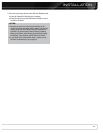
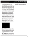
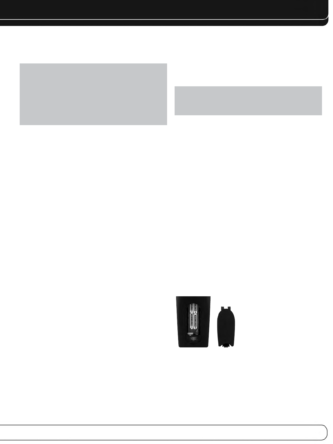
STEP ELEVEN – Insert Batteries in Remote
The AVR 3600 remote control uses four AAA batteries (included).
To remove the battery cover located on the back of the remote,
squeeze the tab and lift the cover.
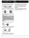
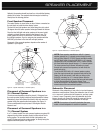
Insert the batteries as shown in Figure 17, observing the correct
polarity.
Figure 17 – Remote Battery Compartment
Point the remote’s lens toward the front panel of the AVR 3600.
Make sure no objects, such as furniture, are blocking the remote’s
path to the receiver. Bright lights, fluorescent lights and plasma
video displays may interfere with the remote’s functioning. The
remote has a range of about 20 feet, depending on the lighting
conditions. It may be used at an angle of up to 30 degrees to either
side of the AVR.