


10
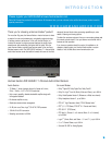
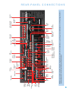
REAR-PANEL CONNECTIONS
Main Power Switch: This mechanical switch turns the power
supply on or off. It is usually left on, and cannot be turned on using
the remote control.
AM and FM Antenna Terminals: Connect the included AM
and FM antennas to their respective terminals for radio reception.
XM Antenna Jack: Plug in an XM Connect-and-Play or Mini-Tuner
antenna module here.
Front, Center and Surround Speaker Outputs: Use two-
conductor speaker wire to connect each set of terminals to the correct
speaker. Remember to observe the correct polarity (positive and negative
connections).
Surround Back/Zone 2 Speaker Outputs: These speaker
outputs are used for the surround back channels in a 7.1-channel home
theater, or may be reassigned to a remote room for multizone operation.
Subwoofer Output: If you have a powered subwoofer with a
line-level input, connect it to this jack.
Preamp Outputs: Connect these jacks to an external amplifier if
more power is desired. The Surround Back/Zone 2 Preamp Outputs
may be used with an external amplifier to power the remote zone of
a multizone system.
Remote Infrared (IR) Input and Output: When the remote IR
receiver on the front panel is blocked, connect an optional IR receiver to
the Remote IR Input jack. The Remote IR Output may be connected to
the Remote IR Input of a compatible product to enable remote control
through the AVR.
Zone 2 Infrared (IR) Input: Connect a remote IR receiver located
in the remote zone of a multizone system to this jack to control the AVR
(and any source devices connected to the Remote IR Output) from the
remote zone.
Remote IR Carrier Output: This output is similar in function to
the Remote IR Output, with the difference that this jack outputs the full
infrared signal as received by the AVR’s IR sensor or the Remote IR
Input, while the Remote IR Output jack outputs a “stripped” signal that
has no carrier frequency.
A-BUS IR Output: This is an additional IR output that may only be
controlled through the A-BUS system. Use it as a dedicated connection
to sources used only with the A-BUS system.
A-BUS Port: Use a Category 5/5e cable to connect this port to
optional A-BUS equipment for multizone operation. When the A-BUS
system is used, it is possible to have a full 7.1-channel system in the
main listening room at the same time the multizone system is in use.
Composite and S-Video 1, 2 and 3 Video Inputs: Use these
jacks to connect your video-capable source components (e.g., VCR,
DVD player, cable TV box) to the receiver. Use only one type of video
connection for each source.
Composite and S-Video 2 Outputs: Connect one of these
analog video outputs to the composite or S-video inputs of a recording
device.A signal is available at these outputs whenever an analog video
source is playing.
Composite and S-Video Monitor Outputs: If any of your
sources use composite or S-video connections, connect one or both of
these monitor outputs to the corresponding inputs on your video display.
If your video display is equipped with HDMI or component video inputs,
these connections are unnecessary, as the AVR 3550HD will convert the
composite or S-video source signal to the correct format for a single
video cable connection to the TV.
HDMI Inputs and Output: HDMI (High-Definition Multimedia
Interface) is a connection for transmitting digital audio and video signals
between devices. Connect up to three HDMI-equipped source devices
to the HDMI inputs using a single-cable connection.
When you connect the HDMI Output to your video display, the
AVR 3550HD will automatically transcode analog video signals to the
HDMI format, upscaling to as high as 1080p.
Analog 1–5: Connect the left and right analog audio outputs of
a source device to any of these inputs.These inputs may be paired
with any video inputs.
NOTES:
• The Analog 3 through 5 connectors physically line up
below the Video 1 through 3 connectors. For convenience,
consider using Analog 3 with Video 1,Analog 4 with Video 2
and Analog 5 with Video 3.
• The Analog 1 and 2 connectors don’t physically line up with
any analog video inputs. Consider using them for audio-only
devices, such as a CD player or cassette tape deck.
• The Analog 2 and 4 inputs are each associated with a set of
outputs. Consider using the Analog 2 connectors for an audio
recorder, and the Analog 4 connectors for a video recorder
(along with the Video 2 connectors).
• You may optionally connect a source to both an analog and
digital audio input. This is useful for making recordings, for
multizone applications or simply as a backup.
Analog 2 and 4 Outputs: Connect either of these analog audio
outputs to the analog audio inputs of a recording device.A signal is
available at these outputs whenever an analog audio source is playing.
Coaxial 1/2 and Optical 1/2/3 Digital Audio Inputs: If a
source has a compatible digital audio output, and if you are not using
an HDMI connection for audio for the device, connect it to one of these
jacks to hear digital audio formats, such as Dolby Digital, DTS and linear
PCM. Use only one type of digital audio connection for each source.
Coaxial Digital Audio Output: If a source is also an audio
recorder, connect the Coaxial Digital Audio Output to the recorder’s input
for improved recording quality. Only PCM digital audio signals (coaxial
and optical) are available for recording.