


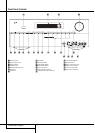
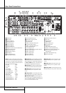
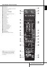

Rear Panel Connections
O
Surround Back/Multiroom Speaker
Outputs: These speaker terminals are normally
used to power the surround back left/surround
back right speakers in a 7.1 channel system.
However, they may also be used to power the
speakers in a second zone, which will receive the
output selected for a multiroom system.
T
o change the output fed to these terminals
from the default of the Surround Back speakers
to the Multiroom Output, you must change a
setting in the
MULTIROOM MENU of the
OSD system. See page 35 for more information
on configuring this speaker output. In normal
surround system use, the brown and black termi-
nals are the surround back left channel positive
(+) and negative (–) connections and the tan
and black terminals are the surround back right
positive (+) and negative (–) terminals.
For multiroom use, connect the brown and black
SBL terminals to the red and black connections
on the left remote zone speaker and connect the
tan and black SBR terminals to the red and black
terminals on the right remote zone speaker.
P
Video 1 Video Outputs: Connect these
jacks to the RECORD/INPUT composite or
S-Video jack on a VCR.
Q
Video 1 Video Inputs: Connect these jacks
to the PLAY/OUT composite or S-Video jacks on
a TV or other video source.
R
Optical Digital Inputs: Connect the
optical digital output from a DVD player, HDTV
receiver, the output of a compatible computer
sound card playing MP3 files or streams, LD
player, MD player or CD player to these jacks.
The signal may be either a Dolby Digital signal, a
DTS signal, a 2 channel MPEG 1 signal, or a
standard PCM digital source.
S
Analog 4 Audio Inputs: Connect these
jacks to the PLAY/OUT audio jacks on a TV or
other audio or video source.
T
Video 2 Video Inputs: Connect these jacks
to the PLAY/OUT composite or S-Video jacks on
a second VCR or other video source.
U
Remote Input and Output: If the AVR’s
front-panel IR sensor is blocked due to cabinet
doors or other obstructions, an external IR sen-
sor may be used. Connect the output of the
sensor to the Remote IN jack.
The Output connection permits the IR sensor in
the receiver to serve other remote controlled
devices. Connect this jack to the “IR IN” jack on
Harman Kardon or other compatible equipment.
V
Zone 2IR Input:Connect the output of an IR
sensor in a remote room to this jack to operate
theAVR’s multiroom control system.
W
Preamp Outputs: Connect these jacks to
a
n optional, external power amplifier for appli-
cations where higher power is desired.
X
HDMI Output: Connect this jack to the
HDMI input on a compatible HDMI-equipped
video display.
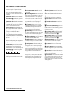
Y
Video 3 Video Inputs: Connect these jacks
to the PLAY/OUT composite or S-Video jacks on
any video source.
Z
A
nalog 3 Audio Inputs:Connect these
jacks to the PLAY/OUT audio jacks on any
audio or video source.
a
HDMI Inputs: Connect the HDMI output of
video sources such as a DVD player, set-top box
or HDTV tuner to either of these jacks.
b
Zone 2 Outputs (AVR 355 only): Connect
these jacks to an optional audio power amplifier
to listen to the source selected by the multiroom
system in a remote room.
c
A-BUS Connector: Connect this jack to an
optional A-BUS-certified remote room keypad or
amplifier to extend the multiroom capabilities of
your AVR. See page 18 for more information on
A-BUS.
d
Remote IR Carrier Output (AVR 355
only): The output of this jack is the full signal
received at the Remote Sensor Window
Ó
or input through the Remote IR Input
U
including the carrier frequency that is removed
from signals at the Remote IR Output
U
. Use
this output to extend IR remote signals to the
input of compatible products by direct connec-
tion or through the use of optional,external IR
“blasters”. If you are in doubt as to which of the
two IR Output jacks to use, we recommend that
you consult with your dealer or installer, or check
with the manufacturer of the external equipment
you wish to control.
e
Video 3 ComponentVideo Inputs (AVR
355 only): These inputs may be used with any
source device equipped with analogY/Pr/Pb or
RGB component video outputs. Do not use these
inputs if HDMI connection is possible, use the
HDMI inputs instead.
f
A-BUS IR Out (AVR 355 only):This output
sends out the remote signal received by anA-
Bus unit.This makes it possible to connect other
Harman Kardon products to theAVR via their
"IR IN" jacks, controlling them from another
room with an A-Bus unit.
g
Main Power Switch: Press this button ON
to apply power to the AVR.When the switch is
ON, the unit is placed in a Standby mode, as
indicated by the amber LED
3
.This button
MUST be ON to operate the unit.To turn the
unit off completely and prevent the use of the
remote control, this switch should be pressed
O
FF.
NOTE: This switch is normally left in the “ON”
position.
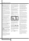
With the AVR’s powerful processor, you may
connect up to three HDMI-equipped source
devices to the HDMI inputs using a single-cable
connection, while benefiting from superior
digital audio and video performance.However, if
your video display is not HDMI-compatible, you
will need to connect the source device to one of
the other source inputs, selecting a coaxial or
optical digital audio input and analog video
input. See the Connections and Installation
sections for more information.
If your video display has an HDMI input,but
some of your sources have only analog video
outputs, you may still rely on just the HDMI
video connection to your display; theAVR will
automatically transcode analog video signals to
the HDMI format.
NOTE ON VIDEO CONNECTIONS: When con-
necting a video source product such as aVCR,
DVD player, satellite receiver, cable set-top box,
personal video recorder or video game to the
AVR 255/AVR 355, you may use either a com-
posite or S-video connection, but not both.
10 REAR PANEL CONNECTIONS