


A
B
C
D
E
F
G
H
I
J
K
L
M
N
O
P
Q
R
R
T
U
V
W
X
AA
AB
AC
AD
AE
FRONT PANEL INFORMATION DISPLAY 7
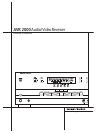
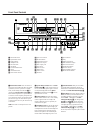
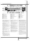
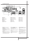
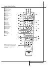
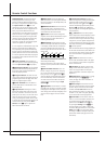
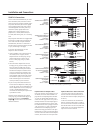
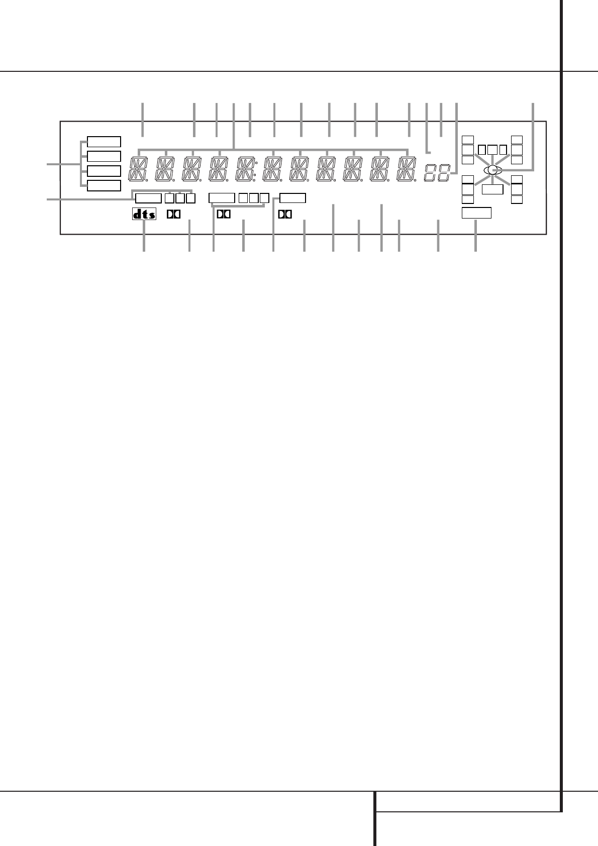
Front Panel Information Display
COAXIAL
THEATER
5 CH STEREO
HALL
3
-
STEREO
PRO LOGIC
DIGITAL
DTS
DOLBY D
PCM
MP3
NIGHT
OPTICAL
ANALOG
LFE
0
CL
0
1 2 3
1 2 3
MEMORY PRESET
SLEEP
AUTO
5.1 LOGIC 7 CM
VMAx NF
MUTE
TUNED ST
A
B
D
E
M
N
K
L
S
T
R
QP
X
W
V
U
F
H
I
J
O
O
R
O
O
LS
O
O
RS
O
O
C
G
RDS
AE
PTY
AD
CT
AC
RT
AB
TA
AA
O
Bitstream Indicators
Optical Source Indicators
DTS Mode Indicator
Dolby Digital Indicator
Coaxial Source Indicators
Dolby Pro Logic Indicator
Analog Input Indicator
Dolby 3 Stereo Indicator
VMAx Mode Indicator
5 Channel Stereo Indicator
Logic 7 Mode Indicators
Hall Mode Indicator
Theater Mode Indicator
Night Mode Indicator
Mute Indicator
Speaker/Channel Input Indicators
Preset Number/Sleep Timer
Preset Indicator
Sleep Indicator
Memory Indicator
Stereo Indicator
Tuned Indicator
Auto Indicator
Main Information Display
Traffic Indicator
Radiotext Indicator
Clock Timer Indicator
Program Type Indicator
RDS Indicator
A
Bitstream™ Indicators:When the input is a
digital source, one of these indicators will light to
display the specific type of signal in use.
B
Optical Source Indicators: These indica-
tors light to show when a Optical Digital Input
has been selected.
C
DTS Mode Indicator: This indicator illumi-
nates when the DTS mode is selected.
D
Dolby Digital Indicator: This indicator illu-
minates when Dolby Digital mode is selected.
E
Coaxial Source Indicators: These indica-
tors light to show when a Coaxial Digital Input
has been selected.
F
Dolby Pro Logic Indicator: This indicator
lights when the Dolby ProLogic mode has been
selected.
G
Analog Input Indicator: This indicator
lights when an analog input source has been
selected.
H
Dolby 3 Stereo Indicator: This indicator
lights when the Dolby 3 Stereo Mode has been
selected.
I
VMAx Mode Indicator: This indicator illu-
minates to show that the VMAx mode is in use.
VMAxF appears when the Far Field VMAx
mode is selected; VMAxN appears when the
Near Field VMAx mode is selected. (See page 24
for a description of the VMAx Modes.)
J
5 Channel Stereo Indicator: This indica-
tor lights when the 5 Channel Stereo mode has
been selected.
K
Logic 7 Mode Indicators: These indicators
illuminate when the Logic 7 mode is in use.
LOGIC 7Cappears for the Cinema version
of Logic 7, LOGIC 7Mappears for the
Music version of Logic 7. (See page 24 for a
description of the Logic 7 Modes.)
L
Hall Mode Indicator: This indicator lights
when the Hall mode has been selected.
M
Theater Mode Indicator: This indicator illu-
minates to show that the Theater mode is in use.
N
Night Mode Indicator: This indicator
lights when the AVR 2000 is in the Night mode,
which preserves the dynamic range of digital
program material at low volume levels.
O
Mute Indicator: This indicator illuminates
to remind you that the AVR 2000’s output has
been silenced by pressing the Mute button
X
. Press the Mute button again to return to
the previously selected output level.
P
Speaker/Channel Input Indicators: These
indicators are multipurpose, indicating either the
speaker type selected for each channel or the
incoming data-signal configuration.The left, cen-
ter, right, right surround and left surround speaker
indicators are composed of three boxes, while the
subwoofer is a single box.The center box lights
when a “Small” speaker is selected, and the two
outer boxes light when “Large” speakers are
selected.When none of the boxes are lit for the
center, surround or subwoofer channels, no
speaker has been selected for that position. (See
page 18 for more information on configuring
speakers.) The letters inside each of the center
boxes display active input channels. For standard
analog inputs, only the L and R will light, indicat-
ing a stereo input.When a digital source is play-
ing, the indicators will light to display the chan-
nels begin received at the digital input.When the
letters flash, the digital input has been interrupt-
ed. (See page 26 for more information on the
Channel Indicators).
Q
Preset Number/Sleep Timer: When the
tuner is in use, these numbers indicate the spe-
cific preset memory location in use. (See page 29
for more information on preset stations.) When
the Sleep function is in use, these numbers show
how many minutes remain before the unit goes
into the Standby mode.