


AVR 1650/AVR 165
7
Rear-Panel Connectors, continued
Rear-Panel Connectors, continued
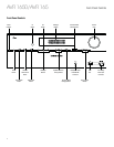
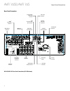
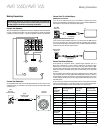
Radio Antenna connectors: Connect the included AM and FM antennas to their
respective terminals for radio reception.
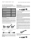
HDMI Monitor Out connector: If your TV has an HDMI connector and you have HDMI or
component video source devices, use an HDMI cable (not included) to connect it to the
AVR’s HDMI Monitor Out connector.
Notes on using the HDMI Monitor Out connector:
• When connecting a DVI-equipped display to the HDMI Monitor Out connector, use
an HDMI-to-DVI adapter and make a separate audio connection.
• Make sure the HDMI-equipped display is HDCP-compliant. If it isn’t, do not connect
it via HDMI; use an analog video connection instead and make a separate audio
connection.
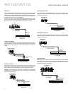
HDMI Input connectors: The HDMI (High-Definition Multimedia Interface
®
) feature is
a connection for transmitting digital audio and video signals between devices. If your
source devices have HDMI connectors, using them will provide the best possible video
and audio performance quality. Since the HDMI cable carries both digital video and
digital audio signals, you do not have to make any additional audio connections for
devices you connect via HDMI connections. See Connect Your Source Devices, on page
13, for more information.
Composite Video Monitor Out connector: If your TV or video display does not have
an HDMI connector, or if your TV does have an HDMI connector but you are connecting
some source devices with only composite video connectors, use a composite video
cable (not included) to connect the AVR’s Composite Video Monitor Out connector to your
TV’s composite video input connector.
DVD Component Video Input connector: If your Blu-ray Disc
™
or DVD player does
not have an HDMI connector but does have a component video connector, using the
component video connector will provide superior video performance. You will also need
to make an audio connection from the player to the AVR.
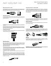
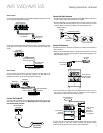
Digital Audio Input connectors: If your non-HDMI source devices have digital outputs,
connect them to the AVR’s digital audio connectors. NOTE: Make only one type of digital
connection (HDMI, optical or coaxial) from each device. See Connect Your Source
Devices, on page 13, for more information.
Video 2 Out connector: Connect an analog video recorder’s video input connector to the
AVR’s Video 2 Out connector. You can record any composite video input signal. NOTE: To
record the audio and video from the source device, connect the AVR’s Video 2 Out Analog
Output connectors to the analog video recorder’s audio inputs.
Composite Video Input connectors: Use composite video connectors for video source
devices that don’t have HDMI or component video connectors. You will also need to
make an audio connection from the source device to the AVR. See Connect Your Source
Devices, on page 13, for more information.
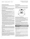
IR Remote In/Out connectors: When the IR Sensor on the front panel is blocked (such
as when the AVR is installed inside a cabinet), connect an optional IR receiver to the IR
Remote In connector. The IR Remote Out connector may be connected to the IR input
of a compatible product to enable remote control through the AVR. See Connect IR
Equipment, on page 15, for more information.
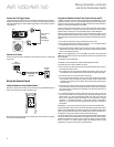
The Bridge IIIP connector: Connect an optional Harman Kardon The Bridge IIIP docking
station to this connector. Insert the plug until it snaps into place in the connector.
IMPORTANT: Connect The Bridge IIIP only with the AVR’s power turned off. See Connect
The Bridge IIIP, on page 15, for more information.
Subwoofer connector: Connect this jack to a powered subwoofer with a line-level
input. See Connect Your Subwoofer, on page 13, for more information.
Analog Audio Input/Output connectors: Use the AVR’s Analog Audio Input/Output
connectors for source devices that don’t have HDMI or digital audio connectors. Use the
Video 2 Out and Tape Out connectors to connect to the audio inputs of a VCR and tape
deck. See Connect Your Source Devices, on page 13, for more information.
Speaker connectors: Use two-conductor speaker wire to connect each set of terminals
to the correct speaker. See Connect Your Speakers, on page 13, for more information.
Optical Digital Output connector: Connect a digital audio recorder’s optical digital
input to the AVR’s Optical Digital Output connector. You can record both coaxial and
optical digital PCM audio signals. (Dolby Digital and DTS
®
bitstreams are not available
for recording.)
Main Power switch: This mechanical switch turns the AVR’s power supply on or off. It is
usually left on and cannot be turned on or off using the remote control.
12V Trigger connector: This connector provides 12V DC whenever the AVR is on. It can
be used to turn on and off other devices such as a powered subwoofer.
AC Input connector: After you have made all other connections, plug the supplied AC
power cord into this receptacle and into an unswitched wall outlet.