


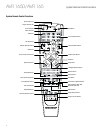
AVR 1650/AVR 165
12
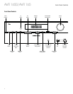
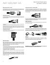
Types of Home Theater System
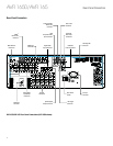
Connections, continued
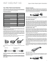
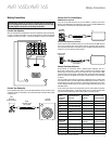
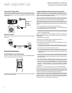
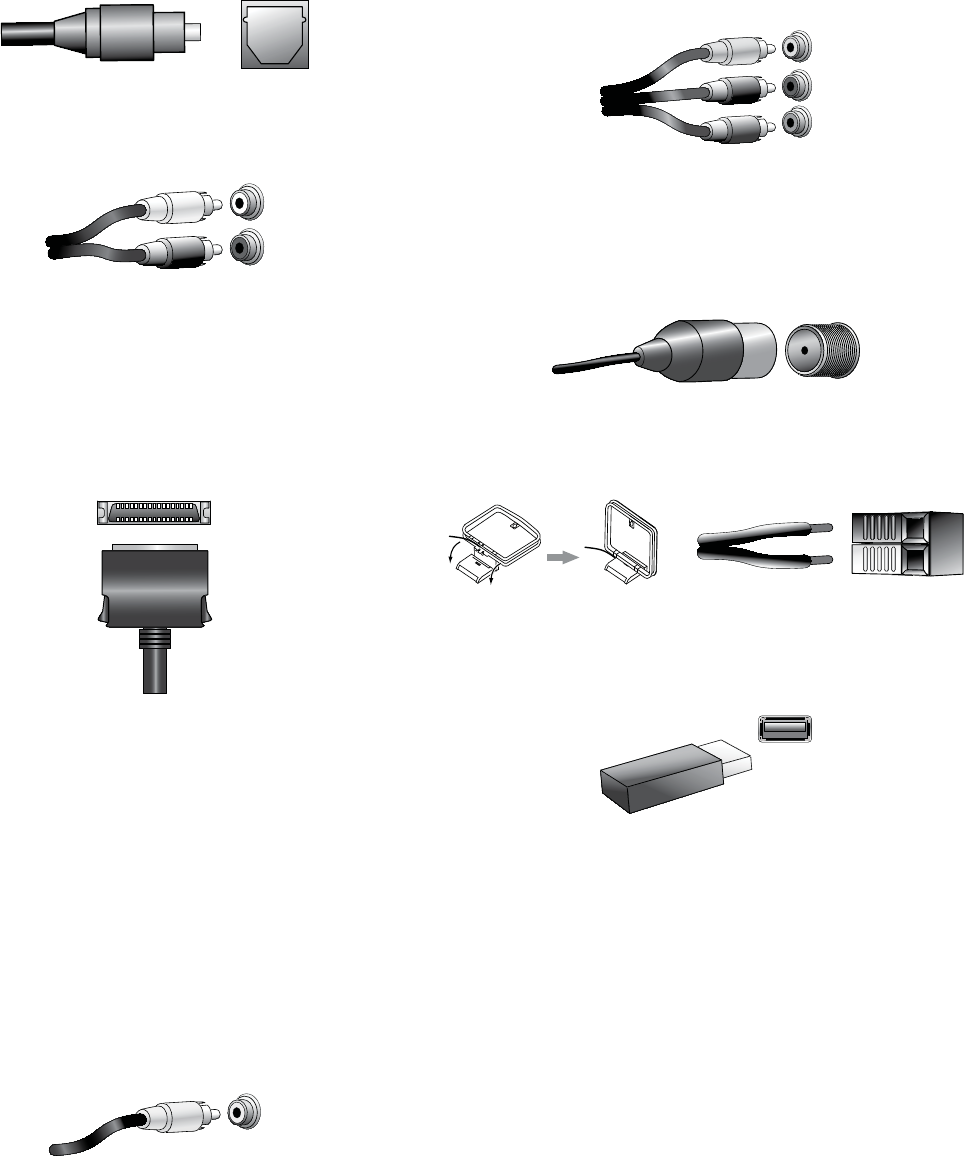
Digital Audio Connections – Optical
Optical digital audio connectors are normally covered by a shutter to protect them from
dust. The shutter opens as the cable is inserted. Optical input connectors are color-
coded using a black shutter, while optical outputs use a gray shutter.
Analog Audio Connections
Two-channel analog connections require a stereo audio cable, with one connector for
the left channel (white) and one for the right channel (red). These two connectors are
attached to each other.
For source devices that have both digital and analog audio outputs, you may make both
connections.
The analog connections also feed the Analog Record Output connectors. You may record
materials from Blu-ray Disc recordings, DVDs or other copy-protected sources using
only analog connections. Remember to comply with all copyright laws if you choose to
make a copy for your own personal use.
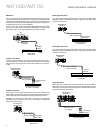
The Bridge IIIP Connection
Your AVR includes a proprietary, dedicated connector for a The Bridge IIIP docking station
(available separately) for the iPod or iPhone.
Video Connections
Many source devices output both audio and video signals (e.g., Blu-ray Disc, DVD
player, cable television box, HDTV tuner, satellite box, VCR, DVR). In addition to an audio
connection as described above, make a video connection for each of these source
devices. Make only one type of video connection for each device.
Digital Video Connections
If you have already connected a source device to one of the AVR’s HDMI input connectors,
you have automatically made a video connection for that device, since the HDMI cable
carries both digital audio and digital video signals.
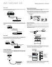
Analog Video Connections – Composite Video
Your AVR uses two types of analog video connections: composite video and component
video.
Composite video is the basic connection most commonly available. Both the chrominance
(color) and the luminance (intensity) components of the video signal are transmitted
using a single cable. The jack is usually color-coded yellow and looks like an analog
audio jack. Do not connect a composite video jack to an analog audio or coaxial digital
audio jack, or vice versa.
Analog Video Connections – Component Video
Component video separates the video signal into three components – one luminance
(“Y”) and two sub-sampled color signals (“Pb” and “Pr”) – that are transmitted using
three separate cables that are color-coded green (Y), blue (Pb) and red (Pr). Component
video cables that join three separate green, blue and red connectors into a single cable
are sold separately.
If your TV or video display has an HDMI connector, we recommend it for the best quality
connection. Your AVR converts component analog video input signals to the HDMI format,
upscaling them to high-definition 1080p resolution.
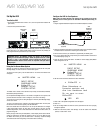
Radio Connections
Your AVR uses separate terminals for the included FM and AM antennas. The FM antenna
uses a 75-ohm F-connector.
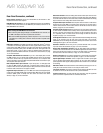
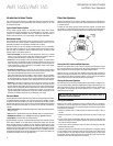
The AM antenna connector uses spring-clip terminals. After assembling the antenna
as shown below, press the levers to open the connectors, insert the bare wires into
the openings, and release the levers to secure the wires. The antenna wires are not
polarized, so you can insert either wire into either connector.
USB Port
The USB port on your AVR is used for firmware upgrades. If an upgrade for the AVR’s
operating system is released in the future, you will be able to download it to the AVR
using this port. Complete instructions will be provided at that time.
IMPORTANT: Do not connect a PC or other USB host/controller to the AVR’s USB
port, or you may damage both the AVR and the other device.