


16
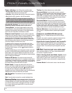
NOTE: Some DVD-Audio, SACD, Blu-ray Disc and HD-DVD players
only output multichannel audio through their multichannel analog
outputs. Make a separate analog audio connection in addition to the
HDMI connection, which is still used for video and to listen to Dolby
Digital, DTS or PCM materials that may be stored on the disc.
The AVR 1600 converts analog video signals to the HDMI format,
including its on-screen menus, but outputs them at their native
resolution.
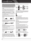
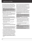
The HDMI connector is shaped for easy plug-in (see Figure 4). If
your video display has a DVI input and is HDCP-compliant, use an
HDMI-to-DVI adapter (not included). A separate audio connection
is required. HDMI cable runs are limited to about 10 feet.
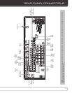
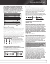
Audio Connections
Left Right
Front (FL/FR)
Center (C)
Surround (SL/SR)
Subwoofer (SUB)
Digital Audio Connections
Coaxial
Optical Output Input
Video Connections
Component Y Pb Pr
Composite
S-Video
Figure 4 – HDMI Connection
If your video display or source device is not HDMI-capable, use one
of the analog video connections (composite or component video)
and a separate audio connection.
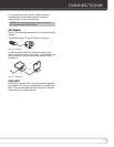
Coaxial digital audio jacks are usually color-coded in orange.
Although they look similar to analog jacks, you should not connect
coaxial digital audio outputs to analog inputs or vice versa. See
Figure 5.
Coaxial
Coaxial digital
audio cable
Figure 5 – Coaxial Digital Audio
Optical digital audio connectors are normally covered by a shutter
to protect them from dust. The shutter opens as the cable is inserted.
Input connectors are color-coded using a black shutter, while outputs
use a gray shutter. See Figure 6.
Optical
Optical digital
audio cable
Figure 6 – Optical Digital Audio
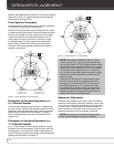
Analog Audio
Analog connections require two cables, one for the left channel
(white) and one for the right channel (red). These two cables are
often attached to each other. See Figure 7.
For sources that are capable of both digital and analog audio, you
may make both connections.
You may only record materials from DVDs or other copy-protected
sources using analog connections. Remember to comply with all
copyright laws, if you choose to make a copy for your own
personal use.
L
R
A
nalog audio
cable (RCA)
Figure 7 – Analog Audio
The 6-/8-Channel Inputs are multichannel analog connections
that are used with high-definition sources that decode the copy-
protected digital content, such as some DVD-Audio, SACD, Blu-ray
Disc and HD-DVD players. See Figure 8. The multichannel analog
audio connection is not required for players compliant with HDMI
version 1.1 or better, or that output linear PCM signals via an HDMI
connection.
Consult the owner’s guide for your disc player for more information,
and see page 25.
Multichannel
analog audio
cable (RCA)
Front Surround Center
White
Red Gray Purple
Blue Green
Subwoofer
Figure 8 – Multichannel Analog Audio
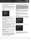
The AVR 1600 has an Auxiliary Audio Input on the rear panel in the
form of a stereo 1/8” mini jack. Connect the headphone output of
any audio source, such as an MP3 player or portable CD player, to
the Auxiliary Audio Input. See Figure 9.
Figure 9 – Auxiliary Audio Input
Video Connections
Many sources output both audio and video signals (e.g., Blu-ray
Disc or DVD player, cable television box, HDTV tuner, satellite box,
VCR, DVR). In addition to the audio connection, make one type of
video connection for each of these sources (only one at a time for
any source).
Digital Video
If you have already connected a source device to one of the HDMI
inputs, you have automatically made a video connection, as the
HDMI signal includes both digital audio and video components.
Analog Video
There are two types of analog video connections used on the
AVR 1600: composite video and component video.
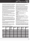
Composite video is the basic connection most commonly available.
The jack is usually color-coded yellow, and looks like an analog
audio jack. Do not plug a composite video cable into an analog
or coaxial digital audio jack, or vice versa. Both the chrominance
(color) and luminance (intensity) components of the video signal
are transmitted using a single cable. See Figure 10.
Composite
video cable
Figure 10 – Composite Video
Component video separates the video signal into three
components – one luminance (“Y”) and two sub-sampled color
signals (“Pb” and “Pr”) – that are transmitted using three separate
cables. See Figure 11.
Component
video cable
Green
Blue
Red
Y
Pb
Pr
Figure 11 – Component Video
COnnECTiOnS