


You are now ready to connect your various components to your receiver.
Before beginning, turn off all components, including the AVR 154,
and
unplug their power cords. Don’t plug any of the power cords back
in until you have finished making all of your connections.
Remember that your receiver generates heat while it is on. Select a
location that leaves several inches of space on all sides of the receiver.
Avoid completely enclosing the receiver inside an unventilated cabinet.
It is preferable to place components on separate shelves rather than
stacking them directly on top of the receiver. Some surface finishes are
delicate. Try to select a location with a sturdy surface finish.
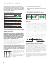
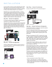
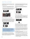
Step One – Connect the Speakers
If you have not yet done so, place your speakers in the listening room
as described in the Speaker Placement section above.
Connect the center, front left, front right, surround left and surround right
loudspeakers to the corresponding speaker terminals on the AVR 154.
See Figure 16. Maintain the proper polarity by always connecting the
positive and negative terminals on each speaker to the positive and
negative terminals on the receiver. Use the Connection Color Guide on
page 16 as a reference.
Figure 16 – Speaker Connections
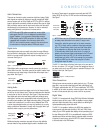
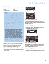
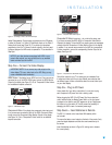
Step Two – Connect the Subwoofer
Connect the Subwoofer Output on the AVR 154 to the line-level input on
your subwoofer. See Figure 17. Consult the manufacturer’s guide for the
subwoofer for additional information.
Figure 17 – Subwoofer Connection
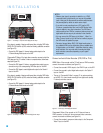
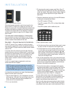
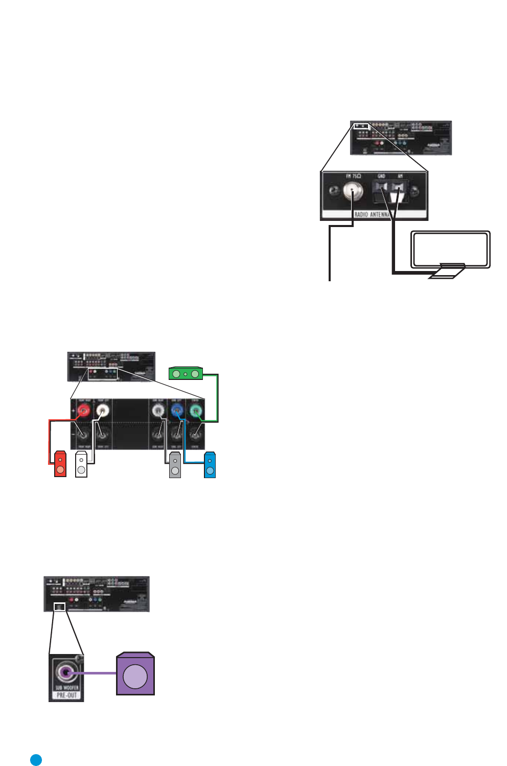
Step Three – Connect the Antennas
Connect the FM and AM antennas to their terminals. See Figure 18.
Figure 18 – Antenna Connections
Step Four – Connect the Source Components
Use the Table A5 worksheet in the Appendix to note which connections
you will use for each of your source devices.
A source is a device where the audio and video signals originate. Some
sources, such as CD players, only offer audio, while sources used for
watching movies or broadcast-television programming deliver a video
signal as well.
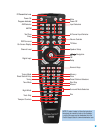
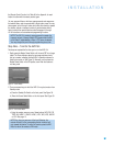
Referring to the photograph of the AVR 154 remote control on page
13, there is a section of 12 buttons near the top of the remote desig-
nated “Input Selectors”: DVD, AM/FM, CD, AUX, TAPE, VID1, VID2, VID3,
HDMI1, HDMI2, HDMI3 and 6CH. Each of these buttons corresponds
to a set of input connectors on the AVR. The set of connectors is
referred to as a “source input”.
The goal of Step Four of the Installation is to match up each of your
source devices, e.g., DVD player and cable television box, with the
correct connectors on the AVR 154.
We recommend that you refer to Table A1 in the appendix when making
these connections. Although you may connect a source to any source
input with the matching types of connectors, by selecting the source
input dedicated to the same type of component, you will be able to
program the AVR’s universal remote to control it, simplifying operation.
The precise connections to be made depend on the capabilities of the
source device and your video display (TV). Select the best audio and
video connections for each source. The types of connections are listed
in order of preference:
Audio Connections
• Choose one digital audio connection: Optical or Coaxial
• Optional, or where digital audio is not available: Analog audio for
making recordings for personal use or as a backup. Analog audio is
required for older analog sources that don’t have digital audio outputs,
such as cassette decks.
FM
AM
AVR 154
AVR 154
SUB
AVR 154
SR
SL
FR FL
C
20
20
INSTALLATION