


REAR PANEL CONNECTIONS 9
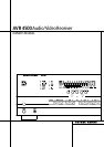
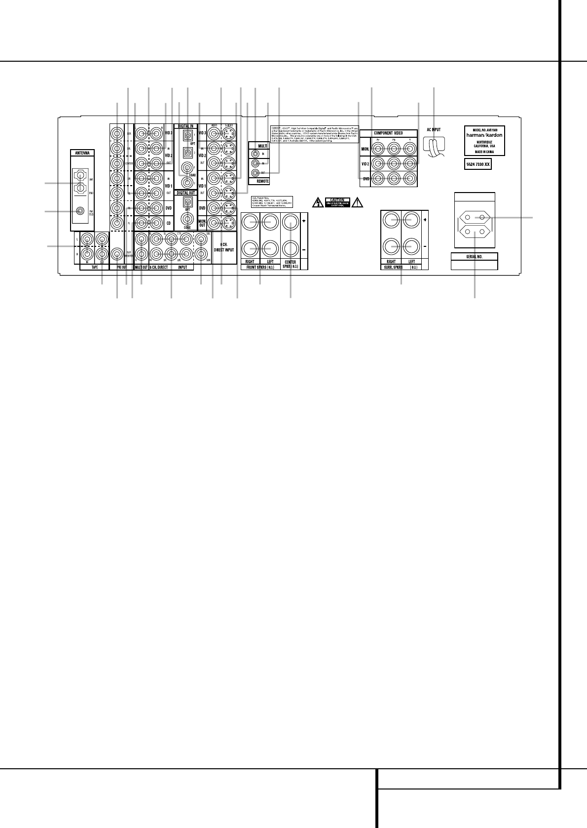
Rear Panel Connections
4
8
9
C
E
F
H
I
J
K
L
M
N
O
PR
S
G
5
Q
7
6
B
A
D
0
b
1
2
3
a
Z
Y
X
W
V
U
T
230 V/50Hz
AC OUTLETS
~230V/50Hz
UNSWITCHED / 100W MAX
SWITCHED / 50W MAX
0
1
2
3
4
5
6
7
8
9
A
B
C
D
E
F
G
H
I
J
K
L
M
N
O
P
Q
R
S
T
U
V
W
X
Y
Z
a
b
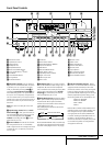
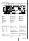
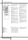
AM Antenna
FM Antenna
Tape Inputs
Tape Outputs
Subwoofer Output
DVD Audio Inputs
CD Inputs
Multiroom Outputs
6-Channel Direct Inputs
8-Channel Direct Inputs
Digital Audio Outputs
Video Monitor Outputs
DVD Video Inputs
Front Speaker Outputs
Center Speaker Outputs
Surround Speaker Outputs
Switched AC Accessory Outlet
Unswitched AC Accessory Outlet
AC Power Cord
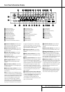
Video 2 Component Video Inputs
Component Video Outputs
DVD Component Video Inputs
Remote IR Output
Remote IR Input
Multiroom IR Input
Video 1 Video Outputs
Video 1 Video Inputs
Video 2 Video Outputs
Video 3 Video Inputs
Video 2 Video Inputs
Optical Digital Inputs
Coaxial Digital Inputs
Video 2 Audio Outputs
Video 2 Audio Inputs
Video 3 Audio Inputs
Video 1 Audio Inputs
Video 1 Audio Outputs
Preamp Outputs
NOTE: To assist in making the correct connec-
tions for multichannel input/output and speaker
connections, all connection jacks and terminals
have been color coded in conformance with the
latest CEA standards as follows:
Front Left: White
Front Right: Red
Center: Green
Surround Left: Blue
Surround Right: Gray
Surround Back Left: Brown
Surround Back Right: Tan
Subwoofer (LFE): Purple
Digital Audio: Orange
Composite Video: Yellow
Component Video “Y”: Green
Component Video “Pr”: Red
Component Video “Pb”: Blue
0
AMAntenna: ConnecttheAM loop antenna
supplied with the receiverto these terminals. Ifan
externalAM antennais used,makeconnections to
the AM and GND terminals in accordance with
the instructions supplied with the antenna.
1
FM Antenna: Connect the supplied indoor or
an optional external FM antenna to this terminal.
2
Tape Inputs: Connect these jacks to the
PLAY/OUT jacks of an audio recorder.
3
Tape Outputs: Connect these jacks to the
RECORD/INPUT jacks of an audio recorder.
4
Subwoofer Output: Connect this jack to
the line-level input of a powered subwoofer.If an
external subwoofer amplifier is used, connect this
jack to the subwoofer amplifier input.
5
DVD Audio Inputs: Connect these jacks to
the analog audio jacks on a DVD or other audio
or video source.
6
CD Inputs: Connect these jacks to the ana-
log output of a compact disc player or CD chang-
er or any other audio source.
7
Multiroom Outputs: Connect these jacks
to an optional audio power amplifier to listen to
the source selected by the multiroom system in a
remote room.
8
6-Channel Direct Inputs: If an external
digital audio decoder is used, connect the out-
puts of that decoder to these jacks.
9
8-Channel Direct Inputs:When an op-
tional, external processor or playback device with
6.1 or 7. 1 audio capability is in use, connect the
Surround Back Left and Surround Back Right
channel outputs of the player to these input jacks
and all other 6.1/7.1 outputs to the appropriate
6-Channel Direct Inputs
8
.
A
Digital Audio Outputs: Connect these
jacks to the matching digital input connector on
a digital recorder such as a CD-R or MiniDisc
recorder.
B
Video Monitor Outputs: Connect this jack
to the composite and/or S-Video input of a TV
monitor or video projector to view the on-screen
menus and the output of any standard Video or
S-Video source selected by the receiver’s video
switcher.