


8 REAR PANEL CONNECTIONS
›
fi
°
⁄
·
a
b
§
•
¡
™
ª
¤
¶
¢
‡
‹
∞
£
fl
‚
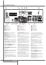
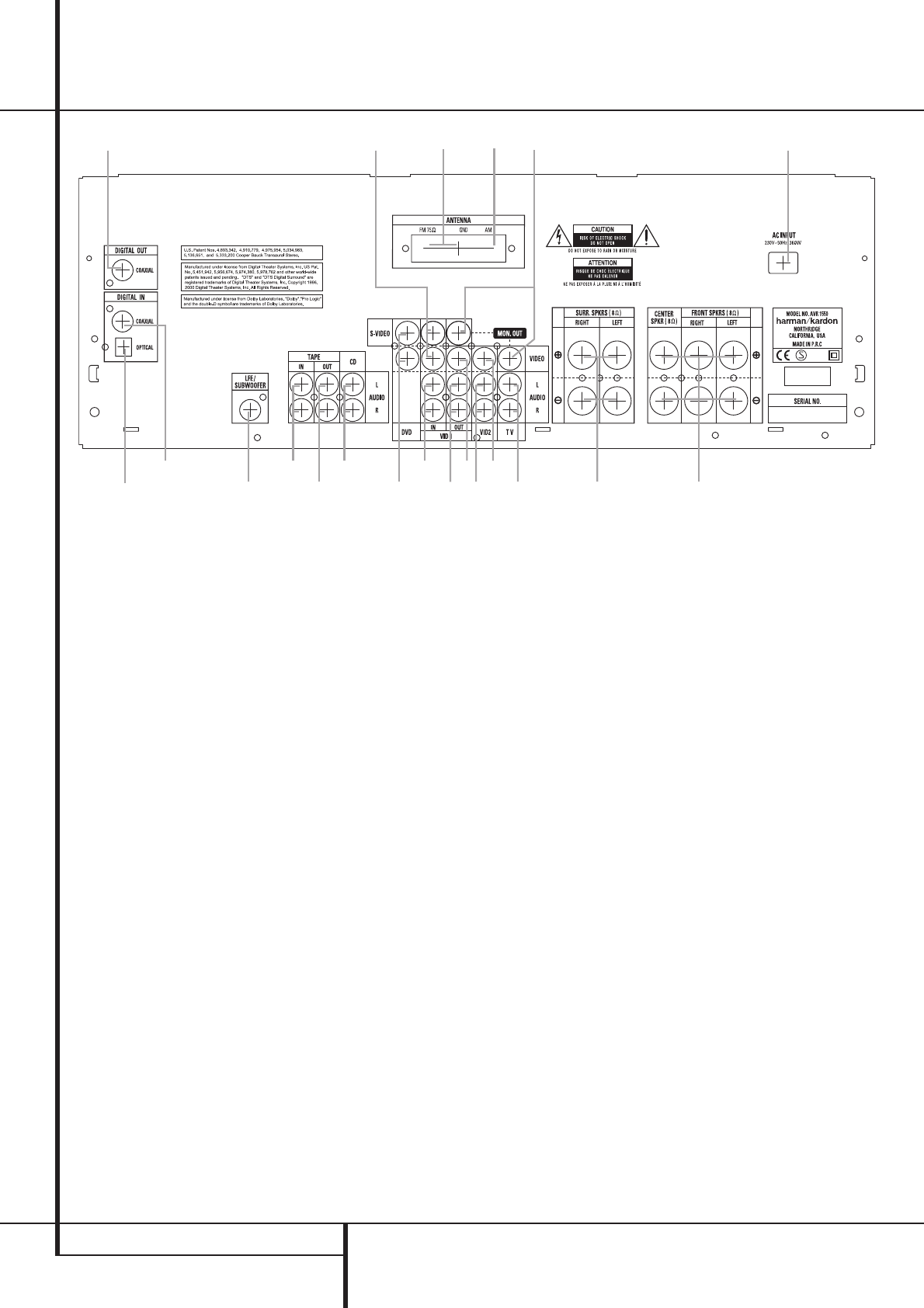
Rear Panel Connections
0
1
2
3
4
5
6
7
8
9
A
B
C
D
E
F
G
H
I
J
K
Tape Inputs
Tape Outputs
Video 1 Audio Inputs
AM Antenna
Video 1 Audio Outputs
Video 2 Audio Inputs
FM Antenna
CD Inputs
Coaxial Digital Audio Outputs
Coaxial Digital Inputs
Subwoofer Output
Video Monitor Outputs
Front/Center Speaker Outputs
Surround Speaker Outputs
TV Audio Inputs
Optical Digital Inputs
AC Power Cord
DVD Video Inputs
Video 1 Video Outputs
Video 1 Video Inputs
Video 2 Video Inputs
0
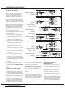
Tape Inputs: Connect these jacks to the
PLAY/OUT jacks of an audio recorder.
1
Tape Outputs: Connect these jacks to the
RECORD/INPUT jacks of an audio recorder.
2
Video 1 Audio Inputs: Connect these jacks
to the PLAY/OUT audio jacks on a VCR or other
video source.
3
AM Antenna: Connect theAM loop antenna
supplied with the receiver to these terminals. If an
external AM antenna is used, make connections to
the AM and GND terminals in accordance with
the instructions supplied with the antenna.
4
Video 1 Audio Outputs: Connect these
jacks to the RECORD/INPUT audio jacks on
a VCR or any other Audio recorder.
5
Video 2 Audio Inputs: Connect these jacks
to the PLAY/OUT audio jacks on a VCR or other
video source.
6
FM Antenna: Connect the supplied indoor or
an optional external FM antenna to this terminal.
7
CD Inputs: Connect these jacks to the ana-
log output of a compact disc player or CD
changer.
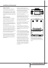
8
CoaxialDigital Audio Outputs: Connect
this jack to the matching digital input connector
on a digital recorder such as a CD-R or MiniDisc
recorder.
9
Coaxial Digital Inputs: Connect the coax
digital output from a DVD player. Do not connect
the RF digital output of an LD player to these
jacks.
A
Subwoofer Output: Connect this jack to
the line-level input of a powered subwoofer. If
an external subwoofer amplifier is used, connect
this jack to the subwoofer amplifier input.
B
Video Monitor Outputs: Connect these
jacks to the composite and/or S-Video input of a
TV monitor or video projector to view the output
of any video source selected by the receiver’s
video switcher.
C
Front/Center Speaker Outputs: Connect
these outputs to the matching + or – terminals
on your front/center speakers.When making
speaker connections, always make certain to
maintain correct polarity by connecting the red
(+) terminals on the AVR 1550 to the red (+)
terminals on the speaker and the black (–) ter-
minals on the AVR 1550 to the black (–) termi-
nals on the speakers. (See page 11 for more
information on speaker polarity.)
D
Surround Speaker Outputs: Connect
these outputs to the matching + or – terminals
on your left and right surround speakers.When
making speaker connections always make cer-
tain to maintain correct polarity by connecting
the red (+) terminals on the AVR 1550 to the
red (+) terminals on the speakers and the black
(–) terminals on the AVR 1550 to the black (–)
terminals on the speakers. See page 11 for more
information on speaker polarity.
E
TV Audio Inputs: Connect these jacks to
the Audio Out jacks on a TV or other video
source.
F
Optical Digital Inputs: Connect the opti-
cal digital output from a DVD player, HDTV
receiver, LD player,MD player or CD player to
these jacks. The signal may be either a Dolby
Digital signal, a DTS signal or a standard PCM
digital source.
G
AC Power Cord: Connect the AC plug to an
unswitched AC wall output.
H
DVD Video Inputs: Connect these jacks to
the composite or S-Video output jacks on a DVD
player or other video source.
I
Video 1 Video Outputs: Connect these
jacks to the RECORD/INPUT composite or
S-Video jack on a VCR.
J
Video 1 Video Inputs: Connect these jacks
to the PLAY/OUT composite or S-Video jacks on
a VCR or other video source.
K
Video 2 Video Inputs: Connect these jacks
to the PLAY/OUT composite jacks on a second
VCR or other video source.