


REAR-PANEL CONNECTIONS 9
REAR-PANEL CONNECTIONS
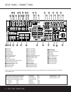
¡ AM Antenna: Connect the AM loop antenna sup-
plied with the receiver to these terminals. If an external
AM antenna is used, make connections to the
AM and
GND terminals in accordance with the instructions sup-
plied with the antenna.
™ FM Antenna: Connect the supplied indoor or an
optional external FM antenna to this terminal.
£ Preamp Outputs: Connect these jacks to an
optional, external power amplifier for applications
where higher power is desired.
¢ Subwoofer Output: Connect this jack to the line-
level input of a powered subwoofer. If an external sub-
woofer amplifier is used, connect this jack to the sub-
woofer amplifier input.
∞ A-BUS Connector:
Connect this jack to an optional
A-BUS
®
-certified remote room keypad or amplifier to
extend the multiroom capabilities of your AVR 430.
See page 38 for more information on A-BUS.
§ Surround Speaker Outputs: Connect these out-
puts to the matching + and – terminals on your sur-
round channel speakers. In conformance with the CEA
color-code specification, the blue terminal is the posi-
tive, or “+” terminal that should be connected to the
red (+) terminal on the Surround Left speaker with
older color-coding, while the gray terminal should be
connected to the red (+) terminal on the Surround
Right speaker with the older color-coding. Connect the
black (–) terminal on the AVR to the matching black
negative (–) terminals for each surround speaker. (See
page 16 for more information on speaker polarity.)
¶ Front Speaker Outputs: Connect these outputs
to the matching + or – terminals on your left and right
speakers. When making speaker connections always
make certain to maintain correct polarity by connecting
the color-coded (white for front left and red for front
right) (+) terminals on the AVR 430 to the red (+)
terminals on the speakers and the black (–) terminals
on the AVR 430 to the black (–) terminals on the
speakers. See page 16 for more information on
speaker polarity.
• Fan Vents: These ventilation holes are the output
of the AVR 430’s airflow system. To ensure proper
operation of the unit and to avoid possible damage to
delicate surfaces, make certain that these holes are
not blocked and that there is at least three inches of
open space between the vent holes and any wooden
or fabric surface. It is normal for the fan to remain off
at most normal volume levels. An automatic tempera-
ture sensor turns the fan on only when it is needed.
ª Center Speaker Outputs: Connect these outputs
to the matching + and – terminals on your center
channel speaker. In conformance with the CEA color-
code specification, the green terminal is the positive,
or “+” terminal that should be connected to the red
(+) terminal on speakers with the older color-coding.
Connect the black (–) terminal on the AVR to the
black negative (–) terminal on your speaker. (See
page 16 for more information on speaker polarity.)
‚ Surround Back/Multiroom Speaker Outputs:
These speaker terminals are normally used to power
the surround back left/surround back right speakers
in a 7.1 channel system. However, they may also be
used to power the speakers in a second zone, which
will receive the output selected for a multiroom system.
To change the output fed to these terminals from
the default of the Surround Back speakers to the
Multiroom Output, you must change a setting in the
Advanced Menu of the OSD system. See page 36 for
more information on configuring this speaker output. In
normal surround system use, the brown and black ter-
minals are the surround back left channel positive (+)
and negative (–) connections and the tan and black
terminals are the surround back right positive (+) and
negative (–) terminals. For multiroom use, connect the
brown and black SBL terminals to the red and black
connections on the left remote zone speaker and con-
nect the tan and black SBR terminals to the red and
black terminals on the right remote zone speaker.
⁄ Switched AC Accessory Outlet: These outlets
may be used to power any device you wish to have
turned on when the AVR 430 is turned on with the
Standby/On Switch 1.
¤ Unswitched AC Accessory Outlet: This outlet
may be used to power any AC device. The power will
remain on at this outlet regardless of whether the
AVR 430 is on or off.
NOTE: The total power consumption of all devices
connected to the accessory outlets should not exceed
100 watts.
‹ AC Power Cord Jack: Connect the AC power
cord to this jack when the installation is complete.
To ensure safe operation, use only the power cord
supplied with the unit. If a replacement is required,
it must be of the same type and capacity.
› Video Monitor Outputs: Connect these jacks to
the composite or S-Video input of a TV monitor or
video projector to view the on-screen menus and the
output of any standard video source selected by the
receiver’s video switcher.
fi DVD Video Inputs: Connect the composite or S-
Video outputs of a DVD player or other video source
to these jacks.
fl Video 1 Video Inputs: Connect the composite or
S-Video PLAY/OUT jacks of a VCR or other video
source to these jacks.
‡ Video 1 Video Outputs: Connect the composite
or S-Video REC/IN jacks of a VCR or other video
recording device such as a DVD recorder or PVR to
these jacks.
° Video 2 Video Inputs: Connect the composite or
S-Video PLAY/OUT jacks of a VCR or other video
source to these jacks.
· Video 2 Video Outputs: Connect the composite
or S-Video REC/IN jacks of a VCR or other video
recording device such as a DVD recorder or PVR to
these jacks.
a Video 3 Video Inputs: Connect the composite or
S-Video PLAY/OUT jacks of a VCR or other video
source to these jacks.
b Component Video Monitor Outputs: Connect
these outputs to the component video inputs of a
video projector or monitor. When a source connected
to one of the
Component Video Inputs cd is
selected the signal will be sent to these jacks.
c Component Video 1 Inputs: These inputs may
be used with any source device equipped with analog
Y/Pr/Pb or RGB component video outputs. The factory
default is for these jacks to be a linked to the DVD
input, but you may change the setting at any time
through the
INPUT SETUP menu. (See
page 21 for more information on configuring the
component video inputs.)
d Component Video 2 Inputs: These inputs may
be used with any video source device equipped with
analog Y/Pr/Pb or RGB component video outputs. The
factory default is for these jacks to be a linked to the
Video 2 input, but you may change the setting at any
time through the
INPUT SETUP menu. (See
page 21 for more information on configuring the com-
ponent video inputs.)
e RS-232 Port: This jack may be used to control
the AVR 430 over a bi-directional RS-232 serial
control link to a compatible computer or programmable
remote control system. Due to the complexity of
programming RS-232 commands we strongly
recommend that connections to this port for
control purposes be made by a trained and qualified
technician. This jack may also link to a compatible
computer to upgrade the software and operating sys-
tem of the AVR 430 when appropriate upgrades are
available.
f Multiroom IR Input: Connect the output of an IR
sensor in a remote room to this jack to operate the
AVR 430’s multiroom control system.