


8 REAR-PANEL CONNECTIONS
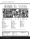
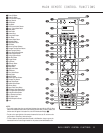
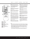
REAR-PANEL CONNECTIONS
¡ AM Antenna
™ FM Antenna
£ Preamp Outputs
¢ Subwoofer Output
∞ A-BUS Connector
§ Surround Speaker Outputs
¶ Front Speaker Outputs
• Fan Vents
ª Center Speaker Outputs
‚ Surround Back/Multiroom Speaker Outputs
⁄ Switched AC Accessory Outlet
¤ Unswitched AC Accessory Outlet
‹ AC Power Cord Jack
› Video Monitor Outputs
fi DVD Video Inputs
fl Video 1 Video Inputs
‡ Video 1 Video Outputs
° Video 2 Video Inputs
· Video 2 Video Outputs
a Video 3 Video Inputs
b Component Video Monitor Outputs
c Component Video 1 Inputs
d Component Video 2 Inputs
e RS-232 Port
f Multiroom IR Input
g Remote IR Input
h Remote IR Output
i Coaxial Digital Audio Output
j Multiroom Audio Outputs
k Optical Digital Audio Output
CD Audio Inputs
DVD Audio Inputs
Optical Digital Audio Inputs
Tape Inputs
Tape Outputs
Coaxial Digital Audio Inputs
Video 1 Audio Inputs
Video 1 Audio Outputs
Video 2 Audio Inputs
8-Channel Direct Inputs
Video 2 Audio Outputs
Video 3 Audio Inputs
42
41
40
39
38
37
36
35
34
33
32
31
NOTE: To assist in making the correct connections for
multichannel input, output and speaker connections,
all connection jacks and terminals are color-coded
in conformance with the CEA standards as follows:
Front Left: White
Front Right: Red
Center: Green
Surround Left: Blue
Surround Right: Gray
Surround Back Left: Brown
Surround Back Right: Tan
Subwoofer: Purple
Digital Audio: Orange
Composite Video: Yellow
Component Video “Y”: Green
Component Video “Pr”: Red
Component Video “Pb”: Blue
REAR-PANEL CONNECTIONS
8 REAR-PANEL CONNECTIONS
NOTE: To make it easier to follow the instructions that refer to this illustration, a larger copy may be downloaded from the Product Support section for this product at
www.harmankardon.com.
430
™
£
¢
∞§
¶
•
ª
⁄
fl
fi
›
·
°c
a
e
d
b
h
g
f
j
k
i
2
‹
‡
38
39
40
41
31
37
36
35
34
33
32
42
¡
‚