


INSTALLATION AND CONNECTIONS 17
INSTALLATION AND CONNECTIONS
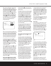
5. Connect the Video Monitor Output › jacks on
the receiver to the composite or S-Video input of your
television monitor or video projector.
6. If your DVD Player has Y/Pr/Pb analog component
video outputs, connect them to the
Component
Video 1 Inputs
c. Although this set of inputs may
be assigned to any of the four video inputs on the
AVR 430, the factory default is for this input to be
assigned to the
DVD Audio Inputs . Remember
to make a digital audio connection between the DVD
player and the AVR, with the
Coaxial Digital Input 1
being the factory default. For information on
changing the input assignments for either the compo-
nent video jacks or the DVD player’s audio connec-
tion, see page 21.
7. If you have other devices with Y/Pr/Pb or RGB
component video outputs, connect the source device
to the
Component Video 2 Inputs d. The audio
connections may be to any of the
Video Audio
Inputs
L or the Optical or Coaxial
Digital Inputs
JK. When using either
of the Component Video Inputs, make certain that
the audio and video inputs are properly configured
in the
INPUT SETUP menu, as described
on page 21.
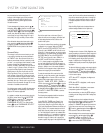
8. If the component video inputs are used, connect
the
Component Video Monitor Outputs b to the
component video inputs of your TV, projector or dis-
play device.
9. If you have a camcorder, video game or other
audio/video device that is connected to the AVR on a
temporary, rather than permanent, basis, connect the
audio, video and digital audio outputs of that device to
the Front-Panel Inputs JKL.A device connected
here is selected as the Video 4 input, and the digital
inputs must be assigned to the Video 4 input. (See
page 21 for more information on input configuration.)
Video Connection Notes:
• When the component video jacks are used, the on-
screen menus are not visible and you must switch
to the standard composite or S-Video input on your
TV to view them.
• The AVR 430 will accept either standard composite,
S-Video or Y/Pr/Pb component video signals.
However, it will not convert composite or S signals
to component video.
• Component or composite video signals may only be
viewed in their native formats.
System and Power Connections
The AVR 430 is designed for flexible use with multi-
room systems, external control components and
power amplifiers.
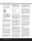
Main Room Remote Control Extension
If the receiver is placed behind a solid or smoked
glass cabinet door, the obstruction may prevent the
remote sensor from receiving commands. In this
event, an optional remote sensor may be used.
Connect the output of the remote sensor to the
Remote IR Input g jack.
If other components are also prevented from receiving
remote commands, only one sensor is needed. Simply
use this unit’s sensor or a remote eye by running a
connection from the
Remote IR Output h jack to
the Remote IR Input jack on Harman Kardon or other
compatible equipment.
Multiroom IR Link
The remote room IR receiver should be connected to
the AVR 430 via standard coaxial cable. Plug the IR con-
nection cable into the
Multiroom IR Input f jack on
the AVR 430’s rear panel.
If other Harman Kardon compatible source equipment
is part of the main room installation, the
Remote IR
Output h jack on the rear panel should be connected
to the IR IN jack on source equipment. This will enable
the remote room location to control source equipment
functions.
NOTE: All remotely controlled components must be
linked together in a “daisy chain.” Connect the
IR OUT
jack of one unit to the IR IN of the next to establish
this chain.
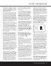
Multiroom Connections
The AVR 430 is equipped with multizone capabilities
that allow it to send a separate audio source to the
remote zone from the one selected for use in the
main room.
Depending on your system’s requirement, three
options are available for audio connection:
Option 1: Use high-quality, shielded audio intercon-
nect cable from the AVR 430’s location to the remote
room. In the remote room, connect the interconnect
cable to a stereo power amplifier. The amplifier will be
connected to the room’s speakers. At the AVR 430,
plug the audio interconnect cables into the
Multiroom
Audio Outputs
j on the AVR 430’s rear panel.
Option 2: Connect the Multiroom Audio Outputs
j on the AVR 430 to the inputs of an optional stereo
power amplifier. Run high-quality speaker wire from
the amplifier to the speakers in the remote room.
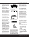
Option 3: Taking advantage of the AVR 430’s built-in
seven-channel amplifier, it is possible to use two of the
amplifier channels to power speakers in the remote
room. When using this option you will not be able to
use the full 7.1-channel capabilities of the AVR 430 in
the main listening room, but you will be able to add
another listening room without external power ampli-
fiers. To use the internal amplifiers to power a remote
zone, connect the speakers for the remote room loca-
tion to the
Surround Back/Multiroom Speaker
Outputs
‚. Before using the remote room you will
need to configure the amplifiers for surround operation
by changing a setting in the Advanced Select menu,
following the instructions shown on page 36.
NOTE: For all options, you may connect an optional IR
sensor in the remote room to the AVR 430 via an
appropriate cable. Connect the sensor’s cable to the
Multiroom IR Input f on the AVR 430 and use the
Zone II remote to control the room volume. Alter-
natively, you may install an optional volume control
between the output of the amplifiers and the speakers.
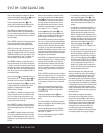
A-BUS
®
Installation Connections
The AVR 430 is among the very few receivers avail-
able today that offer built-in A-BUS Ready operation.
When used with an optional A-BUS keypad or control
module, you have all the benefits of remote zone
operation without the need for an external power
amplifier.
To use the AVR 430 with an approved A-BUS prod-
uct, simply connect the keypad or module that is in
the remote room to the AVR 430 using standard
Category 5 wiring that is properly rated for the in-wall
use specific to the installation. Terminate the wiring
at the receiver end to a standard RJ-45 connector in
compliance with the instructions furnished with the
A-BUS module.
No further installation or adjustment is needed, as the
A-BUS jack on the AVR 430 routes the signals in and
out of the keypad to their proper destination for power,
signal source and control. The output fed to the A-BUS
jack is determined by the AVR 430’s multiroom
system and menus.
Note that the AVR 430’s Multiroom system must be
turned on for any product connected to the
A-BUS
Connector
∞ to operate. See pages 38 and 39
for more information on the Multiroom system and
A-BUS.
36
33
42
39
37
36
32