


INSTALLATION AND CONNECTIONS 19
ENGLISH
Installation and Connections
Important Note
Please open the Harman Kardon Digital Lounge
Accessory Tool Kit before opening any of the
other system components. The Kit contains two
pairs of gloves, that can be used to unpack the
LCD screen without damaging its frame nor
leaving fingerprints on it.
After unpacking the different system components,
and placing them on a solid surface capable of
supporting their weight, you will need to make the
connections to your audio and video equipment.
Equipment Connections
We recommend that you use the supplied cables
when making connections to source equipment
and high quality interconnect cables to additional
equipment to preserve the integrity of the
signals.
When making connections to audio source
equipment or speakers it is always a good
practice to unplug the units from the AC wall
outlet. This prevents any possibility of
accidentally sending audio or transient signals to
the speakers that may damage them.
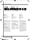
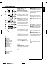
Making the necessary connections to the Digital
Lounge system is done in five easy steps.
1. Connect the front, center and surround speaker
outputs
BCD
to the respective speakers.
Cables that are run inside walls should have the
appropriate markings to indicate listing with any
appropriate testing agency standards. Questions
about running cables inside walls should be
referred to your installer or a licensed electrician
who is familiar with the applicable local building
codes in your area.
When connecting wires to the speakers, be
certain to observe proper polarity. Note that the
positive (+) terminal of each speaker connection
now carries a specific color code. However, most
speakers will still use a red terminal for the
postive (+) connection. Con nect the “negative”
or “black” wire to the same terminal on both the
receiver and the speaker.
We also recommend that the length of cable
used to connect speaker pairs be identical.
For example, use the same length piece of
cable to connect the front-left and front-right
or surround-left and surround-right speakers,
even if the speakers are a different distance
from the Digital Lounge system controller.
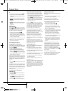
2. Connections to the subwoofer are made via a
line level audio connection from the Subwoofer
Output
7
to the line-level SUB input (purple)
of the subwoofer. Connect at the same time the
Subwoofer Trigger Output
F
to the Trigger
Input of the subwoofer.
3. Connect the supplied FM antenna to the FM
(75 ohm) connection
5
. The FM antenna may
be an external roof antenna, an inside powered
or wire lead antenna or a connection from a
cable system. Note that if the antenna or connec-
tion uses 300-ohm twin-lead cable, you should
use a 300-ohm-to-75-ohm adapter to make the
connection.
4. Your system comes with an combined
HDMI/SP-DIF/Remote in/out cable to make a dig-
ital video connection over HDMI and digital
audio connection from the TV to the DVD re -
ceiver. Connect the HDMI connector on one end
of the wire to the HDMI Output
0
of the receiv-
er and the other end to the HDMI Input
J
of
the screen. Connect the Coaxial Digital connector
on one end of the cable to the Coaxial Digital
Input
8
of the receiver and the other end to the
Coaxial Digital Output
H
of the screen.
Connect one end of the remote connector (the
single pin connector) to the Remote Input of the
screen and the other end to the Remote Input of
the DVD Receiver. Please note that you may run
the remote signal both ways. If you decide that it
is easiest for you to control both screen and
receiver by pointing the remote control towards
the screen, plug the remote cable into the
Remote Control Out of the screen and into the
Remote Control In of the receiver. If your setup
makes it more practical to aim the remote at the
receiver to control both receiver and screen, plug
the remote cable into the Remote Control Out of
the receiver and into the Remote Control In of
the screen.
5. If you use a standard analog TV antenna, con-
nect to the Antenna Input
D
on the rear panel
of the screen. In case you use a DVB-T antenna,
connect that one to the DVB-T Input
Z
on the
rear panel of the screen.
All necessary connections are now made. If you
have additional source components to add,
please refer to the next paragraphs. If not, please
continue with the next chapter of the manual.
Optional Analog Set Top or Cable
Box Connections
If you do not use an aerial antenna but a set top
box or cable box to watch TV, please follow the
instructions below to connect these products.
SCART
If you decide to connect your set top or cable box
to your system using a Scart cable, connect the
Scart output of the set top or cable box to one of
the Scart Inputs
F
on the rear panel of the
screen.
YUV/Component
If you decide to connect your set top or cable box
to your system using a YUV or Component cable,
connect the YUV outputs of the set top or cable
box to the YUV Inputs
E
on the rear panel of
the screen. At the same time connect the analog
audio outputs of the box to the Audio Input for
Component Video Jacks
O
on the rear panel of
the screen, or the digital output of the box to the
Coaxial Digital Input
P
.
S-Video
If you decide to connect your set top or cable box
to your system using an S-Video cable, connect
the S-Video output of the set top or cable box to
the S-Video Input
M
on the rear panel of the
screen. At the same time connect the analog
audio outputs of the box to the Audio Input for
S-Video Jacks
N
on the rear panel of the screen,
or the digital output of the box to the Coaxial
Digital Input
P
.
Composite
If you decide to connect your set top or cable box
to your system using a Composite cable, connect
the Composite output of the set top or cable box
to the Composite/CVBS Input
E
on the rear
panel of the screen. At the same time connect
the analog audio outputs of the box to the Audio
Input for Component Video Jacks
O
on the rear
panel of the screen, or the digital output of the
box to the Coaxial Digital Input
P
.
Important Note: The Coaxial Digital Input
P
of the screen will accept only 2-channel PCM
signals (see item
P
on page 13). To listen to the
multichannel sound from an optical digital out-
put of any external source you can connect it to
the Optical Input
9
of the unit, see next page.
If your source has only a Coaxial Digital output
disconnect the SPDIF cable on the screen (out-
put
H
) and the unit (input
8
), connect the
screen via the analog audio cable to the unit
(Audio Output
A
on screen to the TV Audio
Input
G
on the unit). Then connect the coaxial
digital output of your source to the Coaxial
Digital Input
8
of the unit.
RISKOFELECTRIC SHOCK
DO NO TOPE N
CAUTION
RISKOFELECTRIC SHOCK
DO NO TOPE N
CAUTION
RISKOFELECTRIC SHOCK
DO NO TOPE N
EXT . TRIGGER
INPU T
3-30 V AC
POWER ON
MODE
0007CSK - DigitalLounge 632_640_646 ENG v11.qxp:0007CSK - DigitalLounge 632,640,646 UK 12/06/08 11:10 Side 19 (Sort/Black plade