


DSP420
Digital Signal Processing
In-Wall Loudspeaker System
INSTALLATION & OPERATION
Fitting Instructions
CAUT
ION
RI
SK O
F
EL
ECT
RI
C SH
OCK
D
O
N
OT
O
P
E
N
A
V
IS: R
I
S
Q
U
E
DE
CH
OC ELE
C
T
R
IQ
U
E - N
E
PAS
OU
V
R
I
R
REFE
R TO I
MP
O
R
TAN
T
SA
F
E
TY
I
N
ST
RUCTI
ONS
B
E
F
O
RE
INS
TALLATION
~
1
0
0-24
0V
5
0
-
6
0H
z
O
UT
L
ET
SUITAB
L
E
F
O
R LOADS
UP
TO
1
0
0
0
W 10
A
MAX
IMUM
1
00
-
1
20V
~
or
1
000VA 5A
M
AX
I
MU
M
f
or 22
0
-240V
~
REFER TO INSTRUCTIONS
BEFORE WIRING
AUDIO CONNECTIONS
C
AUT
I
O
N
R
I
SK OF
E
LECT
RI
C
SHOC
K
DO NO
T OPEN
AV
I
S: RI
SQUE DE CHOC
E
LECTRIQUE
- N
E P
AS
OU
V
RI
R
REFER TO IMPORTANT SAFET
Y
INSTRUCTIONS BEFORE
INSTALLATION
~
100-24
0
V 50-
6
0Hz
OUTLET SUITABLE FO
R LOADS UP TO 1000W 10A MAXIMUM
100-120V
~
or
1000VA 5A MAXIMUM
for 220-240V
~
RE
F
ER
TO
IN
S
TR
U
C
TIONS
BE
FO
RE
W
IR
ING
AUD
IO
C
ON
N
EC
TI
O
NS
C
A
U
TI
ON
R
I
SK O
F
EL
EC
T
R
IC
SH
O
C
K
DO
N
O
T
OP
E
N
AV
IS:
RI
SQ
UE
D
E CH
O
C
E
L
EC
T
R
I
Q
U
E
-
N
E
P
A
S
OU
V
R
I
R
RE
F
ER
TO
I
MP
O
RTAN
T
SA
F
ET
Y
IN
S
T
R
U
CTIONS BE
FO
RE
I
NS
TALLA
TION
~
1
00
-2
40
V
5
0-
60
H
z
OU
TL
E
T
SU
I
TAB
L
E F
O
R
LOA
D
S U
P
TO 1
000W
10
A MA
XI
M
UM
10
0
-120V
~
o
r
1
000
V
A
5
A
MA
X
IMU
M
for
2
20
-2
40V
~
1
3
2
4
5
6
7
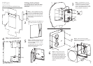
Step 1: Use the template (provided
as part of the packaging) to mark wall
for cut-out (far left). Position equally
between battens. Use this alternative
method (left) to mark battens prior to
wall covering.
Step 2: Ensure that 12in (300mm) of
each cable is present in the wall cut-
out.
Step 3: Fix back-box into cut-out.
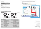
Thread cables through correct holes
in back box: audio/comms cables
come in from the top; power from the
bottom (see separate sheet for power
wiring installation instructions).
Step 4: Tidy and clamp all cables. Fit
covers to power and audio boxes.
Step 5: Carefully connect power and
audio between loudspeaker unit and
back box. An IEC connector is used
for power; DSUB
for digital audio. Be sure to install the
digital cable with the choke on the
end next to the speaker.
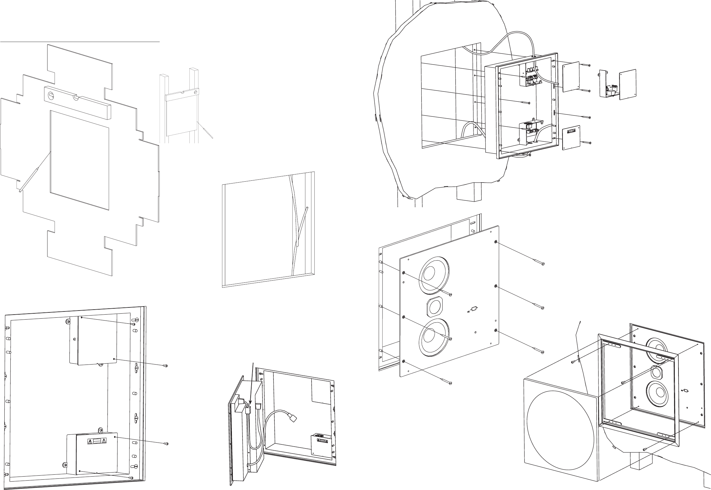
Step 6: Neatly position power
and comm cables and push the
loudspeaker unit all the way in so
that it locates on the pegs in the
back-box. Secure using the six M5
x 12 button-head socket screws
supplied, Meridian part number
H61513.
See separate sheet for important safety
instructions! Illustrations are not all to the
same scale.
Step 7: Secure frame and fit grille.
Grille can be carefully removed using the
extraction tools supplied.