6.25 x 8.00 label
XPA 1002 Audio Power Amplifier
The Extron XPA 1002 is a half-rack width, two-channel, stereo audio power amplifier that outputs 60 watts per channel (8-ohm speakers) or 100 watts per
channel (4-ohm speakers). The XPA 1002 utilizes Extron’s patented CDRS™ Class D Ripple Suppression technology to reduce EMI. The audio level
adjustment feature prevents the occurrence of audio clipping.
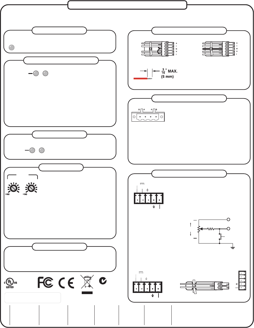
C Connect the sleeve to
ground (Gnd). Connecting
the sleeve to a negative (-)
terminal will damage the
audio output circuits.
These front and rear panel LEDs (representing output channels 1
and 2) light red under three circumstances:
• When audio clipping occurs, the corresponding channel’s
LED blinks once per clip occurrence.
• When the amplifier overheats, both LEDs are lit. The LEDs
are not lit after the amplifier cools down and recovers from
the overheated condition.
• When DC output is detected, the amplifier is malfunctioning
and the LED for the corresponding channel is lit. Power down the
amplifier and power it back up. If the LED still remains lit after a
power cycle, the amplifier requires servicing.
1 2
LIMITER/
PROTECT
Limiter/Protect indicator LEDs
Audio input wiring
Level adjustment
These front and rear panel LEDs
(representing input channels 1 and 2)
light green only when an input signal is
detected on the corresponding channel.
Signal indicator LEDs
1 2
SIGNAL
LEVEL
1 2
0 0
Level adjustment (channels 1 and 2) —
Use a Tweeker or small screwdriver to
adjust the audio input level for the
corresponding channel. The analog
potentiometers control the level from -=
(full attenuation) to 0 dB.
To adjust the XPA amplifier's input level, do the following:
1. Make sure that the source signal is active.
2. Before powering up the amplifier, adjust the output level(s) to
the lowest setting (fully counterclockwise).
3. Power up the amplifier.
4. Adjust level(s) by turning the adjustment clockwise until audio
distortion begins to occur, then back off the adjustment
(turning counterclockwise) until the distortion disappears.
L R
L R
Unbalanced Stereo Input
Balanced Stereo Input
Ring
Sleeve (s)
Tip
Sleeve
Tip
Sleeve
Tip
Tip
Ring
Do not tin the wires!
Audio output wiring
Remote control connector
Stereo audio output connector (channels 1
and 2) — Marked "1" and "2" for the output
channels, wire the included 4-pole, 5.08 mm
screw lock captive screw connector to output
stereo audio through either channel. Observe
the correct polarities for each channel. Speaker output is rated at 100
watts per channel (4-ohm speakers) or 60 watts per channel (8-ohm
speakers).
N You must use Class 2 wiring for this output to comply with
UL requirements.
W Do not tie channel outputs 1 and 2 to each other or to
ground. Doing so will short out the outputs and/or damage
the amplifier.
Remote control connector — The 3.5 mm 5-pin
captive screw receptacle is used to remotely
control two functions through contact closure:
1. As shown on the left, pins 1, 2, and 3 control
volume by varying the DC voltage from 0 V (full
attenuation) to 10 V (maximum volume) with full
muting in effect when pin 2 is connected to
ground (pin 3). See the circuit diagram below.
N Maximum volume
output is dependent
on input level
adjustment.
2. As shown below, pin 5
connected to ground
(pin 4) places the amplifier
in standby mode. Standby mode turns off all output(s),
although the amplifier is still receiving power. Use the
included 2-pin, 3.5 mm captive screw connector plug to remotely
ground pin 5.
GND
10K OHMS
2K OHMS
MAX
2 VOL/MUTE
3
1 10 V
MIN
MUTE SWITCH
This front panel LED lights red when the amplifier
exceeds the recommended ambient temperature for
optimal lifetime. The LED turns off after the amplifier
cools down sufficiently. See the User’s Manual.
Over Temp indicator LED
OVER
TEMP
1 2 3 4 5
STANDBY
Remote Switching to Standby Mode
The XPA goes into standby mode after approximately one hour of
inactivity. The XPA comes out of standby mode approximately one
second after detecting an input signal (unless in manual standby —
see “Remote control connector”).
Automatic standby mode
1 2 3 4 5
STANDBY
VOL/MUTE
10V 50 mA
1 2 3 4 5
STANDBY
VOL/MUTE
10V 50 mA
CLASS 2 WIRING
1 2
OUTPUT
33-1470-01 Rev. A
09 08
0.05" rounding
6.25" W x 8.00" High
Black text on white stock
for placement on bare metal.
N15779
www.extron.com
Extron USA - West
Headquarters
+800.633.9876
Inside USA / Canada Only
+1.714.491.1500
+1.714.491.1517 FAX
Extron USA - East
+800.633.9876
Inside USA / Canada Only
+1.919.863.1794
+1.919.86 3.1797 FAX
Extron EMEA
+800.3987.6673
Inside Europe Only
+31.33.453.4040
+31.33.453.4050 FAX
Extron Asia
+800.7339.8766
Inside Asia Only
+65.6383.4400
+65.6383.4664 FAX
Extron Japan
+81.3.3511.7655
+81.3.3511.7656 FAX
Extron China
+400.883.1568
Inside China Only
+86.21.3760.1568
+86.21.3760.1566 FAX
Extron Middle East
+971.4.2991800
+971.4.2991880 FAX
17TT
AUDIO/VIDEO
APPARATUS


