


Setup Guide — TP Receivers
This card provides instructions for an experienced
installer to set up and operate the TP Receiver Series
products.
Refer to www.extron.com for the complete user’s
manual.
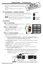
Pre-installation — Jumper settings
The TP R BNC A and TP R BNC AV are factory configured to receive
RGB video. They can receive component, S-video or composite video
by changing jumper J3 located on the main board.
N
If using the TP R BNC AV with an older TPX 88X transmitter,
download the TP Receivers User’s Manual at www.extron.com
and refer to the audio jumper settings.
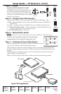
Installation
Step 1 — Mounting
Turn off or disconnect all equipment power sources
and mount the receiver as required.
Step 2 — Connect input
Connect the RJ-45 cable (from a TP transmitter)
to the Input port on the TP R.
Terminate the ends of the cable to the same
standards.
Step 3 — Connect outputs
Attach the applicable output cables (video, audio),
depending on the TP R model.
a. Composite video output connector — Connect to the single female BNC
connector (VIDEO) for composite video output (TP R BNC AV Only) or to
either the R, or G, or B connectors (TP R BNC A Only).
b. S-video output connector — Connect to the R (C-chroma) and G (Y-luma)
connectors.
c. Component video — Connect to the R (R-Y), G (Y) and B (B-Y) connectors.
d. RGBHV Video — Connect to the R, G, B, H, V connectors.
e. RGBS video — Connect to the R, G, B, H/V connectors.
f. High resolution video output connector — Connect to the 15-pin HD
connector (TP R 15HD A only).
g. Audio connector — Connect an audio device accepting line level analog
audio to the unbalanced stereo audio RCA connectors (TP R BNC A and
TP R BNC AV) or to the line level stereo 3.5 mm, 5-pole captive screw
connectors as shown.
5
Pin
1
2
3
6
7
8
4
Wire color
White-green
NOTE If using Enhanced
Skew-Free™ A/V cable, use th
e
TIA/EIA T568A standard only.
Green
White-orange
White-blue
Orange
White-brown
Brown
Wire color
T568A T568B
White-orange
Orange
White-green
White-blue
Green
White-brown
Brown
Side
Blue Blue
Insert
Twisted Pair
Wires
Pins:
12345678
RJ-45 Connector
C
For unbalanced audio, connect both sleeves to the center (ground
)
contact. DO NOT connect the sleeves to the negative (-) contacts.
Unbalanced Output
Balanced Output
Do not tin the wires!
Tip
Ring
Tip
Ring
L R
Sleeves
NO GROUND HERE
NO GROUND HERE
Tip
Tip
L R
Sleeves
RGB
J3
1
2
3
Component,
S-video,
Composite
J3
1
2
3
Continued on other side