


1
MPA 401-70V and MPA 401-100V • Setup Guide
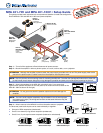
This guide provides basic instructions for an experienced installer to install and congure the
Extron MPA 401-70V and MPA 401-100V mini power ampliers.
INPUTS
OUTPUT
50/60 Hz
100-240V .3A
2
1
3
4
L
R
L
R
L
R
L R
L
R
AUDIO
VID
1
2
3
4
Y
/VID
B-Y
H/
HV
R
/R-Y
V
G
/Y
B
/B-Y
RS-232
LAN
RESET
ACT
LINK
DVI-I
YC
SDI
R-Y
/C
RGB/R-Y,Y,B-Y/YC/VID
I
N
P
U
T
O
U
T
P
U
T
I
N
P
U
T
O
U
T
P
U
T
POWER
12V
1.5A MAX
OUTPUT
70V
INPUTS
L
(MONO)
(MONO)
R
REMOTE
VOL/MUTE
MPA 401-70V
R
L
CLASS 2 WIRING
DO NOT GROUND
OR SHORT
SPEAKER OUTPUTS!
10V 50mA
US
LISTED
17TT
AUDIO/VIDEO
APPARATUS
®
Extron
SI 3CT LP
Full-Range
Ceiling Speakers
Extron
MPA 401
Mini Power
Amplier
Extron
DVS 304 DVI AD
Digital Video
Scaler
with Audio
Audio
Flat Panel
Display
(DVI)
DSS Receiver
(S-video)
Laptop
(RGB)
DVD
(Component)
VCR
(Video)
Extron VC 50
Volume Controller
Extron
MLC 104 IP Plus
Controller
POWER
12V
1.5A MAX
CLASS 2 WIRING
L
(SUMMED)
(SUMMED)
R
V
C
G
MPA 401-100V
R
L
10V 50mA
REMOTE
100V OUTPUT
INPUTS
VC 50
Extron
VOLUME
DBS RECEIVER
CONFIG
DISPLAY
MLC 104 IP
VOLUME
1
2
3
4
ON
OFF
Step 1 — Turn all of the equipment off and disconnect all power sources.
Step 2 — Mount the amplier in either a plenum space, on a rack, under a desk, or on a projector.
ATTENTION: Although the amplier is plenum rated, the power supply provided with it is not. The power supply must not be
placed in the plenum space. Cables to and from the amplier must be plenum rated.
NOTE: Use only the two round mounting holes for mounting the MPA 401. The other four (hexagonal) holes anchor stand-offs
for the internal circuit boards. Using them may damage the amplier and does not provide secure mounting for the unit.
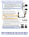
Step 3 — Attach the speakers to the MPA 401 using the 2-pole, 5 mm screw-lock
captive screw speaker receptacle on the rear panel. (The old and new silk screens for the
MPA401-100V are shown to the right).
ATTENTION: Do not ground or short the speaker outputs as this will damage the
amplier.
NOTE: The mono audio speaker receptacle may be labeled in one of two ways (see
the images to the right). The wiring and function are the same whichever way the
product is labeled.
Step 4 — Attach sources to the MPA 401 unit from the audio source or projector.
The three rear panel audio inputs can be used individually or together:
z One pair of RCA receptacles (unbalanced)
z One 3.5 mm stereo tip-ring-sleeve receptacle (unbalanced)
z One 3.5 mm, 5-pole captive screw receptacle (balanced or unbalanced)
Balanced Mono Input
Tip
Ring
Sleeve
LR
Balanced Stereo Input
Tip
Ring
Tip
Ring
Sleeves
LR
Unbalanced Stereo Input
Tip
Slee
ve
Slee
ve
Tip
LR
Unbalanced Mono Input
Tip
Sleeve
LR
CLASS 2 WIRING
100V OUTPUT
Tip (+)
Sleeve ( )
RCA Connector
Sleeve ( )
Ring (R)
Tip (L)
3.5 mm TRS Connector
OUTPUT
100V