


TECHNICAL SPECIFICATIONS CB259X
CINEMA SYSTEMS
DESCRIPTIVE DATA contiued
DESCRIPTIVE DATA
Configuration 2-way
Powering Mode Passive
Recommended High-Pass
Frequency (24 dB/Octave) 30 Hz
Cabinet Type (shape) Rectangular with externally mounted
horn/driver assembly
Enclosure Materials 3/4-in Medium Density Fiberboard
with 15 mm baltic birch baffle
Finish Textured black
Connectors 2 terminal barrier strip
Dimensions inches millimeters
Height 54.19 1376
Width 24.44 621
Depth (min.) 17.75 451
Depth (max.) 24.94 633
Weights pounds kilograms
Net Weight 160.5 73.0
Shipping Weight 177.5 80.8
Part Number 999356
LF Subsystem & Loading 2x15-in vented
HF Subsystem & Loading 1x2-in exit compression driver on
CD horn
• For medium cinemas
• Passive 2-way screen channel loudspeaker
• Requires only one amplifier channel and no external crossover
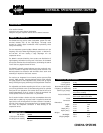
The CB259X two-way passive screen loudspeaker system fills medi-
um-sized theaters with all the high-impact, full-range sound
encoded on today’s digital soundtracks while reproducing voices
clearly and naturally.
The two component system includes a BV253C vented dual 15-in low
frequency unit and a HK294 high frequency system - a medium for-
mat 90°x40° HF horn loading a large diaphragm 2-in exit
compression driver.
The HK294’s constant directivity horn assures even distribution of
high frequency information to every seat in the house. Its shortened
horn throat minimizes horn throat distortion, eliminating the 700 Hz
“honk” that has plagued cinema HF horns.
The BV253C’s optimally vented enclosure uses the enclosure’s reso-
nance to increase LF response while limiting driver excursion. This
method produces less distortion and minimizes driver strain while
extending LF response to the lowest octaves.
The sections are integrated via an internal passive crossover/filter
network. EAW’s complex, computer-designed passive filter networks
are tightly aligned to the loudspeakers they control and go beyond
merely dividing the signal, performing critical equalization functions.
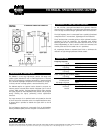
The adjustable steel bracket attaching the HF horn to the LF enclo-
sure can be positioned at one of three mounting points for optimum
front/rear HF horn placement. The bracket allows the HF horn to be
aimed independently of the LF section in both the horizontal and
vertical planes and can be locked once it is positioned.
The LF section includes a barrier strip that accommodates bare wire,
tinned leads or spade lugs. A jumper cable is supplied to extend the
signal chain to the HF component. The input connector is located on
the side of the enclosure for convenient access in cramped installa-
tion areas. HF component connection is made directly on the
compression driver.
APPLICATION
PRODUCT INFORMATION