


6
© 2002 Directed Electronics, Inc
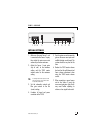
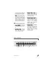
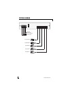
Power Connector
1.
RReemmoottee TTuurrnn OOnn OOuuttppuutt
- This
output is intended to be the remote
turn on for the system amplifiers
and has a built in delay. Two to
three seconds after the 2500
receives a (+)12V turn on signal, it
will send a (+)12V turn on signal
to the amplifiers. This feature is
designed into the 2500 to elimi-
nate system turn on pops that can
occur when several components
turn on at the same time.
2.
((++)) 1122VV CCoonnssttaanntt PPoowweerr
- This is
the main power input for the 2500
and must be connected to a
(+)12V constant power supply. DO
NOT connect this to a switched
(+)12V source or the system may
pop when the key is turned off.
3.
RReemmoottee TTuurrnn OOnn IInnppuutt
- This is the
input for turning on the 2500. It
should be connected to the (+)12V
remote turn on output of the system
head unit. The 2500 has a built in
turn off delay to prevent turn-off
pops. When the remote in signal
from the head unit shuts off, the
amplifiers will turn off immediately
and the 2500 will stay on for two to
three seconds before turning off. This
feature is designed into the 2500 to
eliminate system turn off pops that
can occur when several components
turn off at the same time.
DO NOT connect this to a (+)12V
constant power supply.
4.
GGrroouunndd
- Connect this terminal to a
quality ground location (preferably
the chassis of the head unit) which
must itself be properly grounded to
the vehicle chassis. It is not recom-
mended that the factory radio
ground be used for any audio
components.
5.
PPoowweerr FFuussee
- This fuse protects the
2500's on-board electrical compo-
nents. Never replace this fuse with
one of higher value or damage to
the 2500 could occur and result in
loss of your warranty.
6.
FFrroonntt AAmmpplliiffiieerr OOuuttppuutt
- These are
output jacks for sending the audio
signal to the front amplifier.
7.
RReeaarr AAmmpplliiffiieerr OOuuttppuutt
- These are
output jacks for sending the audio
signal to the rear amplifier.
8.
SSuubbwwooooffeerr AAmmpplliiffiieerr OOuuttppuutt
- These
are output jacks for sending the
audio signal to the subwoofer
amplifier.
9.
SSoouurrccee 22 IInnppuutt
- This is the input for
the secondary source unit.
10.
SSoouurrccee 11 IInnppuutt
- This is the input for
the main source unit.
REAR PANEL FEATURES