


4 - The PatchMix DSP Mixer
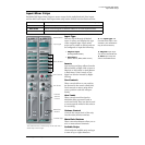
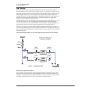
Mixer Strip Creation
40 Creative Professional
Meter Inserts
Keeping track of signal levels is important in any audio system, be it analog or digital.
You want to keep the signal levels running as close to maximum in order to achieve high
resolution and low noise. On the other hand, you don’t want the signal level so high as
to cause clipping. To help you maintain optimum signal levels, we have included Peak
Level Meters, which can be dropped into any insert location.
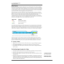
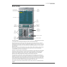
The insert meters are of the “peak hold” type. The topmost bar in the meter holds its
highest level for a second to let you see transients that would otherwise be too quick for
the eye. A numeric readout above the meter shows the peak-hold level in dB.
The peak meters are also color-coded to indicate the signal strength. The chart below
outlines the meanings of the colors. Avoid lighting the topmost red bar, as this indicates
distortion of the signal. Click on the clip indicator to turn it off.
One of the most obvious uses of the insert meters is to set input levels. On the analog
inputs, the analog-to-digital converter (ADC) is one of the most critical points in the
signal path. You want the input signal level to drive the 24-bit ADCs into their optimum
range without clipping. A reading of 0dB on an input meter indicates signal clipping.
The insert meters are also useful to monitor incoming digital signals such as ADAT,
ASIO or S/PDIF to make sure the mixer is receiving a proper signal level. They’re also
great for troubleshooting, since you can place them virtually anywhere in the mixer.
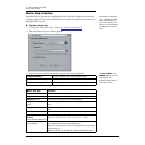
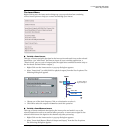
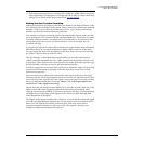
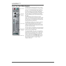
To Insert a Meter
1. Right-Click on an Insert location of the mixer strip. A pop-up dialog box appears.
2. Select Insert Peak Meter. A stereo peak meter appears in the insert location.
3. Select Effect in the Main Section. The meters are now shown in high resolution in
the TV screen.
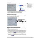
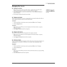
To Set the Input Levels of a Strip
1. Select the topmost Insert location on a mixer strip and insert a meter (see above).
2. Left-click on the meter insert to see the meter in the TV screen.
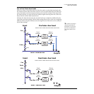
f Input too weak?
Use -10 Input setting.
Output too weak?
Use +4 Output setting
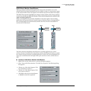
3.
Feed your audio signal to the input of the mixer strip. The meter should now show
the signal level.
4. Adjust the output level of the external device (synthesizer, instrument, preamp, etc.)
feeding the AudioDock or 0202 Daughter Card. The meter should be in the yellow
region most of the time with occasional forays into the red. If the clip indicator ever
comes on, reduce the signal level.
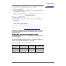
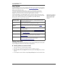
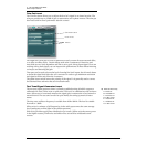
Meter Color Indicates
E Red Indicates signal clipping.
E Yellow Good strong signal level.
E Green Signal is present.
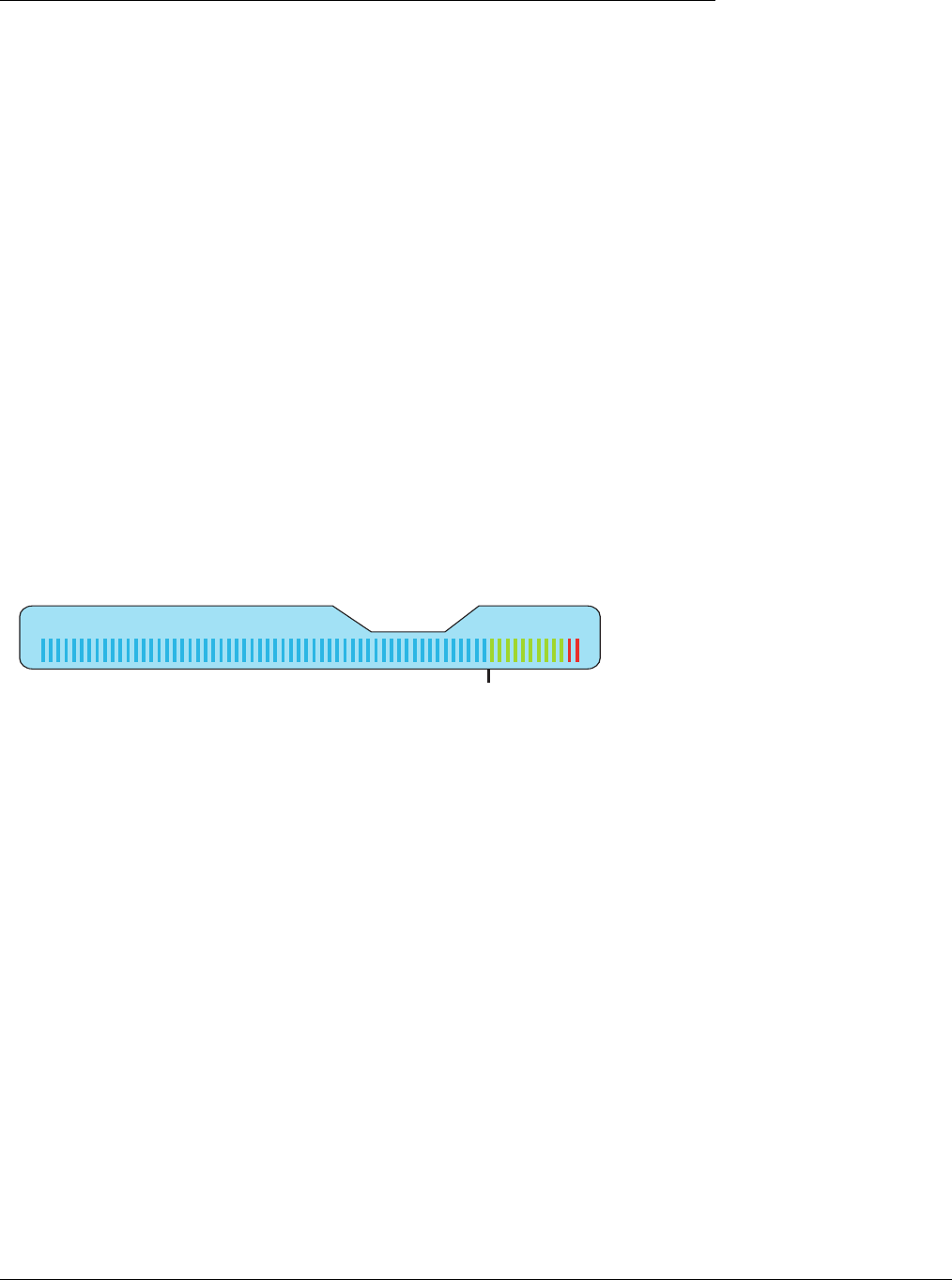
--12dB
Level
10203040506070
Each bar of the meter equals 1dB. The yellow bars begin at -12dB below full scale.