


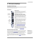

3 - PCI Card & Interfaces
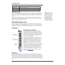
The AudioDock
20 Creative Professional
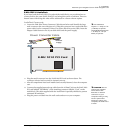
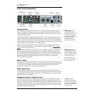
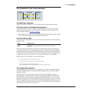
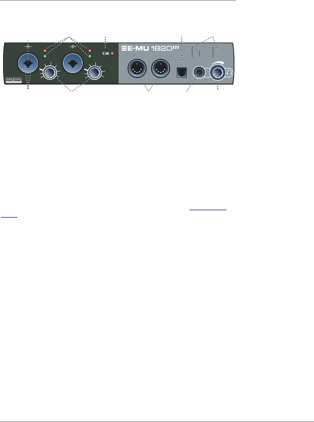
Front Panel Connections
Preamp Section
Warning: Some
microphones cannot
tolerate phantom power
and may be damaged.
Check the microphone’s
specifications and
requirements before
using phantom power.
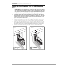
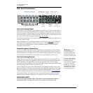
The front panel mono Mic/Line inputs A & B can be used as balanced microphone
inputs, hi-Z guitar pickup inputs, or line level inputs. The Neutrik combination jack
accepts microphones using a standard XLR connector or line level/hi-Z inputs using a
1/4 inch TRS/TS connector.
The superb-sounding mic preamps are designed by TF Pro®. Each preamp has a level
control which sets the preamp gain from +20dB to +55dB for the XLR input and from
-10dB to +25dB for the line input. The line markings around the knobs are calibrated in
10dB increments. The heavy hash marks on the gain controls indicate unity analog gain
to the converter inputs (~5dBV input = 0dBFS output).
A phantom power switch enables +48 volt phantom power supplied to both micro-
phones. A red LED illuminates to indicate phantom power is enabled. See Phantom
Power for additional information.
Warning #2: After
turning phantom power
off, wait two full minutes
before recording to allow
the DC bias to drain.
The audio mutes for a
second when phantom
power is turned on.
Each microphone input has its own input level and clipping indicators. The green LED
indicates presence of signal and illuminates at -12 dB below clipping. The red LED
indicates that the signal is clipping the input. These LEDs monitor the signal directly at
the analog-to-digital converters and before any processing by the rest of the system.
When setting the levels for signals being sent into the AudioDock, the red level
indicators should never flash.
MIDI 1 In/Out
MIDI input and output ports allow you to interface any type of MIDI equipment such as
keyboards, effect units, drum or guitar controllers. The MIDI drivers were installed when
you installed your PatchMix DSP software and the MIDI ports will appear in your
system control panel under “Sounds and Audio Devices”.
S/PDIF Optical Out
The front panel S/PDIF connector is an optical TOSLINK output which, by default,
carries a digital copy of the main output pair. This output is a convenient way to master
to a portable DAT, MD recorder or other media. This S/PDIF output can also be freely
assigned in the mixer application.
Headphone Output & Volume Control
f Tip: Since the
headphone output can
be placed into any insert
location, you can use it to
monitor or troubleshoot
the signal flow.
The headphone output drives standard stereo headphones and the adjacent volume
control sets the listening level. The headphone amplifier can drive headphones with
impedance as low as 24 ohms. The headphone output uses a high-current version of the
high-quality output amplifiers used on the other channels. For this reason it has a very
clean signal that can be used as another stereo output if you need it. This output is freely
assignable in the mixer application.
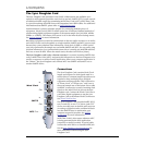
A Line
Mic
Clip
-12 dB
+20 dB
+2
5 dB
+55 dB
-10 dB
Line -
Mic -
B
Line
Mic
Clip
-12 dB
+20 dB
+2
5 dB
+55 dB
-10 dB
48V
MIDI 1
In
Out
Out
S/PDIF
MIDI CLOCK SMPTE
1
2
48
192
IN
OUT
9644.1LCK
EXT
2
Insert 1/4"
Plug for Line Level
Phantom
Power On/Off
Signal/Clip
Indicators
Input Gain
Controls
MIDI #1
I/O Jacks
Headphone
Output
Headphone
Volume
S/PDIF
Optical Out
LED
Indicators
Insert XLR Plug
for Mic Level
+20dB to +55dB Gain
-10dB to +25dB Gain