


3133501
Alarm Relay Closure
A mechanical relay is used in the AnaSat
®
SSPA for alarm indication. The red LED mounted on
the SSPA is illuminated whenever a problem exists and the relay has closed.
The alarm relay has normally closed contacts, so it defaults to the alarm state when power is off.
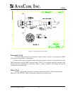
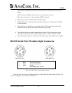
The alarm relay is accessible through the 18-pin connector mounted on the SSPA chassis. See Figure 10
for a diagram of the pins in this connector.
Monitored Values
The following analog inputs are monitored and can result in Alarm closure if out of range:
PA temperature
-5V DC supply (used as a bias voltage in the power amp stages)
+5V DC supply
PA Stage voltages
Main +13V DC supply
The following digital inputs are monitored:
Cooling fan failure
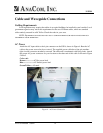
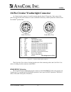
Data Terminal Connection
Using a serial cable with a connector on one end that matches y our terminal equipment (either a
“dumb” terminal or a computer running terminal emulator or modem software), connect the 6-pin or
18-pin weathertight circular connector to the other end, following figure 10 below.
Terminal Display
The ASCII terminal display gives an accounting of SSPA alarms and status, example:
100W EC-Band SSPA REV:04 S/N:012345
TXREQ on | TX ON AIR
ALARM:CLEAR
TXG 50.0 TXout 47
TXpk 48
TEMP: 13C FANERR:clear P12V:13.4 P11V:PA12 P5V: 5.0 N5V:-5.4
PA 1: 0.0 PA 2: 0.0 PA 3: 0.0 PA 4: 0.0 PA 5: 0.0 PA 6:13.0
• The top line shows the SSPA model and serial number.
• The second line gives the only changeable operating parameter: ON or OFF. This can be
set using the TX command: example TX ON, TX OFF.
ANACOM AnaSat
®
SSPA 19