


3
UDR800 RECEIVER
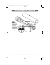
1. Rack Mounting the Receiver
There are 2 options available (as accessories) for rack mounting the UDR800 receiver: single
or side-by-side with another UDR800 receiver.
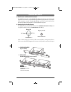
A. Single Mounting (RPK89)
: Remove the receiver SIDE MOUNT CLIPS (1) from each side of
the receiver (as shown) and slide in the optional wider RACK EARS (2).
(see page 4)
B. Side-by-Side Double Mounting (RPK90): After removing the SIDE MOUNT CLIPS (1) from
both UDR800 receivers, join the two receivers with the JOINING CLIP (3) and attach the
narrow RACK EARS (4) as shown.
(see page 4)
(Note: Do not mount the receiver in a rack directly above an amplifier or other source of high
heat — this could degrade the performance of the UDR800. Always ensure adequate airflow an
d
heat dissipation in any rack configuration.)
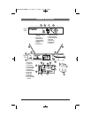
2. Powering the Receiver
Plug the 22V DC ADAPTER (28) provided into the DC INPUT JACK (6) on the back of the
receiver. Then plug the power supply into an AC outlet. Press the POWER SWITCH (9) once
to turn on the receiver. The POWER “ON” LED (10) will now light and the receiver is operational.
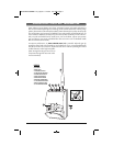
3. Antennas
The UDR800 receiver is equipped with attached dual FOLDING ANTENNAS (11). Optimal
positions of the antennas are 45° from the receiver (or 90° from each other). For maximum
range, it is always best to maintain a line-of-sight (no obstructions) between the receiver
antennas and the transmitter at all times whenever possible.
4. Adjusting the Mute Level/RF Squelch
The MUTE LEVEL/RF SQUELCH (24) can be changed anytime during the main screen display to
quiet the receiver in high noise environment conditions. The control ranges are from level 0 to
level 5. The level should be adjusted to a lower number to the minimum RF squelch setting at
which the RF INDICATOR (19) will remain on while your transmitter is in normal use, up to the
maximum operating range anticipated in use for your application. However, in areas of high
RF activity, the squelch control may need to be adjusted to a higher number. If the transmitter is
off and the receiver signal RF INDICATOR (19) or the diversity A or B INDICATOR (20) flickers
or stays on continuously, the squelch should be adjusted to a higher number to stop the
flickering. Be careful not to select too high a number setting as this may reduce the operating
range to below what is needed. A range walk test will help in selecting the proper level. If the
range is not critical, note that a higher level (maximum squelch) setting will also yield a quieter
mute function, which might be desired in certain applications. The squelch level is factory
preset at maximum sensitivity and operating range (i.e. level 0 for minimum squelch level —
maximum usable range).
(Note: For easier intuitive operation, the MIN and MAX indicators for this control refer to the
minimum and maximum operating range settings, not to the actual mute levels selected, which
are the opposite as per above.)
WirelessManualNEW11.10_Layout 1 11/18/11 2:01 PM Page 5