Installation Instructions
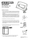
1. Unscrew wing nut and remove threaded pin to separate the mounting base from
the horn. Use the base as a template for the mounting holes. Drill three
mounting holes and attach the base using appropriate hardware (not included).
See Figure 1
IMPORTANT: Make sure the base sits flat on the mounting surface. Tightening
the base down on an uneven surface could cause the base to fracture.
The speaker can be mounted to an I-beam flange using Bogen's accessory
BC1 Beam Clamp. The slot in the base also allows strapping to be used as a
means of mounting the horn (use a strapping material capable of supporting
the weight of the speaker and any external loads on the horn such as wind).
2. Reassemble horn on to base after it has been mounted.
3. Remove the plastic cover to make the electrical connections (see Figure 2).
Connect the 70V or 25V “hot” lead to the #1 terminal and the system common
lead to the #2 terminal. Follow this pattern on all similar speakers to ensure
proper phasing; however, the speakers will work perfectly well if the connec-
tions are reversed.
4. Adjust the tap selector switch to the desired wattage using the chart below and
secure the plastic cover back in place.
5. Loosen Wing Nut, tilt and swivel the horn to the desired orientation, then
re-tighten. Hand tighten wing nuts. Do not use pliers or tools.
KFLDS30T
Wide Dispersion, 30W,
Horn Loudspeaker
© 2005 Bogen Communications, Inc.
Specifications subject to change without notice.
54-2138-01A 0505
Figure 1
Figure 2
BC1 Beam Clamp
(optional accessory)
TAP
SET
1
2
3
4
5
6
7
8
25V
WATTS
70V
WATTS
1.8
3.7
7.5
15
30
*
*
*
.25
.5
.9
1.8
3.7
7.5
15
*
IMPORTANT:
DO NOT
use positions
marked as "
*
"
ELECTRICAL
CONNECTION
TAP SET
CONTROL