


m-ACR Automatic Charging Relay
Features
• Automatically combines batteries during charging, isolates batteries when discharging
• The Start Isolation option protects electronics from voltage sags and spikes during engine cranking
• Supports alternators up to 65 Amps
• Ignition protected—safe for installation aboard gasoline powered boats
• For 12 or 24 volt systems
• Dual Sensing—senses charging on either battery bank
Specications
Intermittent Rating (5 min.) 115A
Continuous Rating 65A
Operating Current (Combine) 90mA
Operating Current (Open) 15mA
Cable Size (to meet current ratings) 6 AWG (16mm²)
Maximum Cable Size 1/0 AWG (50mm²)
Terminal Stud Size 1/4"-20
Maximum Torque 60 in-lbs (6.8 Nm)
Relay Contact Position 12V DC 24V DC
Combine (30 sec.) 13.6V DC 27.2V DC
(2 min.) 13.0 V DC 26.0V DC
Open Low (10 sec.) 12.35V DC 24.7V DC
(30 sec.) 12.75V DC 25.5V DC
Over Voltage Lockout 16.0V DC --
Under Voltage Lockout 9.5V DC 19.0V DC
Under Voltage Reset 10.0V DC 20.0V DC
Regulatory
E marked for Ignition Protection, Meets ISO 8846 and SAE J1171 external ignition protection requirements
Rated IP67----temporary immersion up to 1 meter for 30 minutes
980014350 Rev.001
m-ACR Mounting
• To avoid corrosion to connecting wires and terminals, mount in a dry and protected location if possible. Avoid locations
directly above the battery banks.
m-ACR Electrical Connections
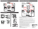
• The wiring diagrams illustrated on the back page represent common installations and are not meant to
beaguideforwiringaspecicvessel.
• The 7601 m-ACR is not intended to carry starting currents. Use a battery switching system with a
combine batteries/parallel function if batteries may need to be combined for emergency starting.
Caution: Disconnect battery connections before beginning the installation.
m-ACR Voltage Sensing
• The 7601 m-ACR will sense a charge being applied to either battery bank.
* Larger wire sizes may be required to minimize voltage drop in long wire runs.
For more information please use the Circuit Wizard at www.circuitwizard.bluesea.com
Wire Size and Fuse Rating Chart
Charging Amps Min. Wire Size* (AWG) Fuse Rating Min. Wire Size* (Metric)
≤30 #10 40A-50A 6 mm²
≤50 #8 60A-65A 10 mm²
≤65 #6 90A-100A 16 mm²
Use the wire sizing chart below to select the appropriate wire sizes to prevent overheating the m-ACR.
m-Series, Dual Circuit Plus™ Battery Switch 6011 (Included with 7649 Mini Add-A-Battery)
Features
• Switches two battery banks simultaneously with one ON/OFF switch while maintaining battery bank
isolation, minimizing the risk of a dead start battery
• The COMBINE BATTERIES function parallels two battery banks in the event of a low battery
• Ignition protected—safe for installation aboard gasoline powered boats
Specications
Cranking Rating (10 sec.) 1,000 Amps
Cranking Rating (1 min.) 650 Amps
Intermittent Rating (5 min.) 450 Amps
Continuous Rating 300 Amps
Maximum Voltage 32 Volts
Cable Size to Meet Ratings 4/0 AWG (120mm²)
Terminal Stud Size 3/8"-16 (M10)
Maximum Torque 120 in-lbs (13.56 Nm)
Regulatory
E marked for ignition protection, meets UL1500 and SAE J1171 external ignition
protection requirements
Rated IP66---protected against powerful water jets
m-ACR minimum connections for operation:
• Connect one battery bank positive to one of the 1/4”-20 studs.
• Connect the other battery bank positive to the other 1/4”-20 stud.
• Both positive connections should be made through appropriately sized circuit protection to meet
ABYC recommendations. See “Wire Size and Fuse Rating” chart, above, for suggested fuse ratings.
• Connect the quick connect terminal marked GND (ground) to the DC system ground through
a10Ain-linefusetopreventfaultcurrentsfromowinginthiswire.
m-ACR optional connection:
To enable start isolation:
• Connect a wire from the quick connect terminal marked SI (starting isolation) to the terminal or wire
running from the start key switch to the starter solenoid (see back for wiring diagram). This connection
can be made at the start key switch or at the starter solenoid, but must be to the line that is positive only
when cranking. Connection to a line that is positive while the engine is normally running will prevent the
charging relay from working properly.
Features and Specications for
m-ACR 7601 and Mini Add-A-Battery 7649
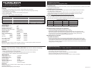
LED Status Chart
LED BATTERY STATUS REASON
Solid ON Combined Charging
Single Flash (15 sec.) Isolated Standby
Double Flash Isolated (Start Isolation) Start Isolation wire is energized
Triple Flash Isolated (Under Voltage Lockout) One or both batteries are below
9.5V (12V System) 19V (24V System)
• Turn all loads off before turning the battery switch to OFF.
• Do not switch to OFF while the engine is running.
• Mount the battery switch in an easily accessible location close to the batteries.
• Attach one 4/0 AWG cable per terminal to meet ratings.
• Terminals must be attached under nut and lock washer. Torque to 120 in-lb (13.56 Nm)
Installation Instructions
m-Series, Dual Circuit Plus™ Battery Switch 6011 (Included with 7649 Mini Add-A-Battery)
Installation Instructions
m-ACR Automatic Charging Relay 7601