


E-7
ENGLISH
Warning
• To prevent short circuit, remove the key from the ignition and
disconnect the battery’s (-) terminal.
• This unit is designed for negative ground 12 V DC operation
only. You can not use it for 24 V or other types of car batter-
ies.
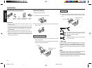
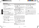
Connection procedure
Caution
• DO NOT connect any speaker wires to the metal body or chas-
sis of the vehicle.
• DO NOT connect the speaker common (-) wires to each other.
• Connect each speaker wire directly to each speaker termi-
nal.
• All speaker common (-) wires must remain floating.
i.e. No Common Connections or connections to vehicle grd .
• Connect each pair of speaker leads only to a single speaker
(or speaker system) that has an impedance of least 4 ohms,
as well as 40-watt power-handling capability.
• Do not connect speaker leads to any inputs on external am-
plifiers. This will cause damage to the internal amplifier of this
unit.
1 Make sure the car’s ignition key has been removed.
2 Disconnect the negative (-) terminal of the car’s bat-
tery.
3 Connect the wiring harness wires in the following
order : Ground wire (Black), +12V Constant Power
Supply (Yellow), +12V Accessory/Switched (Red) and
Power Antenna/Amplifier Turn On (Blue), and tape each
so they do not come in contact with each other.
4 Connect the speaker wires of the wiring harness.
5 Connect the car’s antenna terminal to the antenna
socket of the unit.
6 Connect the detachable wire harness to the unit.
7 Reconnect the negative (-) terminal of the car’s bat-
tery.
8 Start the car’s engine.
9 Make sure the unit operates properly.
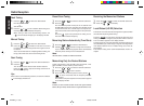
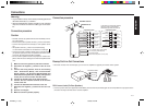
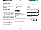
Connections
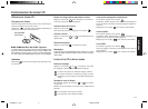
Preamp Out/Line Out Connections
• Since this unit has Line Level Outputs, you can use an amplifier to upgrade your vehicle stereo system.
(White)
(White/Black)
(Gray)
(Gray/Black)
(Green)
(Green/Black)
(Violet)
(Violet/Black)
Left
Speaker
Right
Speaker
Do Not
Connect
Front Left
Speaker
Front Right
Speaker
Rear Left
Speaker
Rear Right
Speaker
(White)
(White/Black)
(Gray)
(Gray/Black)
(Green)
(Green/Black)
(Violet)
(Violet/Black)
Do Not
Connect
2-speaker System4-speaker System
+12V Constant Power Supply (Yellow)
+12V Accessory/Switched (Red)
Ground Wire (Black)
Power Antenna/Amplifier
Turn
On (Blue)
ANTENNA PLUG
ANTENNA SOCKET
In the case of a 2-speaker system,
tape the ends of unconnected
terminals to prevent short circuit
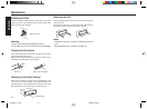
External Amplifier
Rear Speaker
White (Left)
Red (Right)
RCA Line-out Jacks
RCA Line-out Jacks (For Rear Speakers)
• Connect a patch cable (not supplied) from the White (left rear channel) and Red (right rear channel) RCA line output jacks of the
unit to the line input terminals of the external amplifier.
Connection procedure
RPD540_p.1-9 (E) 9/9/99, 3:23 PM7