


6 EUROLIVE F1320D User Manual
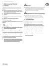
2. Control Elements and
Connections
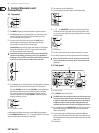
2.1 Top panel
Fig. 2.1:
(1)
(2)
(3)
First group control
(1) The POWER LED lights up when the loudspeaker is put into operation.
(2) The CLIP LED lights up when signal distortion occurs. Reduce the volume
with the LEVEL control until the CLIP LED does not light up any more,
oroccasionally lights up at signal peaks.
(3) To set the volume of the LINE or MIC signal, use the LEVEL control.
Thelefthalf of the control range is for attenuating the LINE signal.
Therighthalf is for raising the level of the MIC signal.
Level adjusting: Turn the LEVEL control whose signal you want to adjust
slowly to the right until the CLIP LED (2) lights up only at signal peaks.
TheLED is not supposed to glow continuously.
◊ We would like to draw your attention to the fact that extremely loud
sound levels may damage your hearing as well as your headphones/
loudspeakers. Turn the LEVEL control fully to the left before you switch
on the unit. Be careful to select a suitable volume at all times.
Fig. 2.2:
(4)
Equalizer
(4) The F1320D features a 3-band sound control. Each band provides a maximum
boost/cut of 15dB. At center position the equalizer has a atresponse.
The upper (EQ HIGH) and the lower band (EQ LOW) are shelving lters that
boost and cut all frequencies above and below the crossover frequency.
Thecrossover frequencies of the upper and lower bands are at 12kHz
and 80Hz, respectively. The mid band (EQ MID) is a peak lter the center
frequency of which is at 2.5kHz.
Fig. 2.3:
(5)
(6)
Feedback lter (notch lter)
Feedback may occur at high volume levels or under dicult stage situations.
Usethe FEEDBACK FILTER function ( (5), (6) ) to reduce feedback. To learn more
about the feedback lter, read section3.4 “Notch lter.”
(5) This switch turns on the feedback lter.
(6) This control adjusts the center frequency of the feedbacklter.
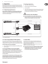
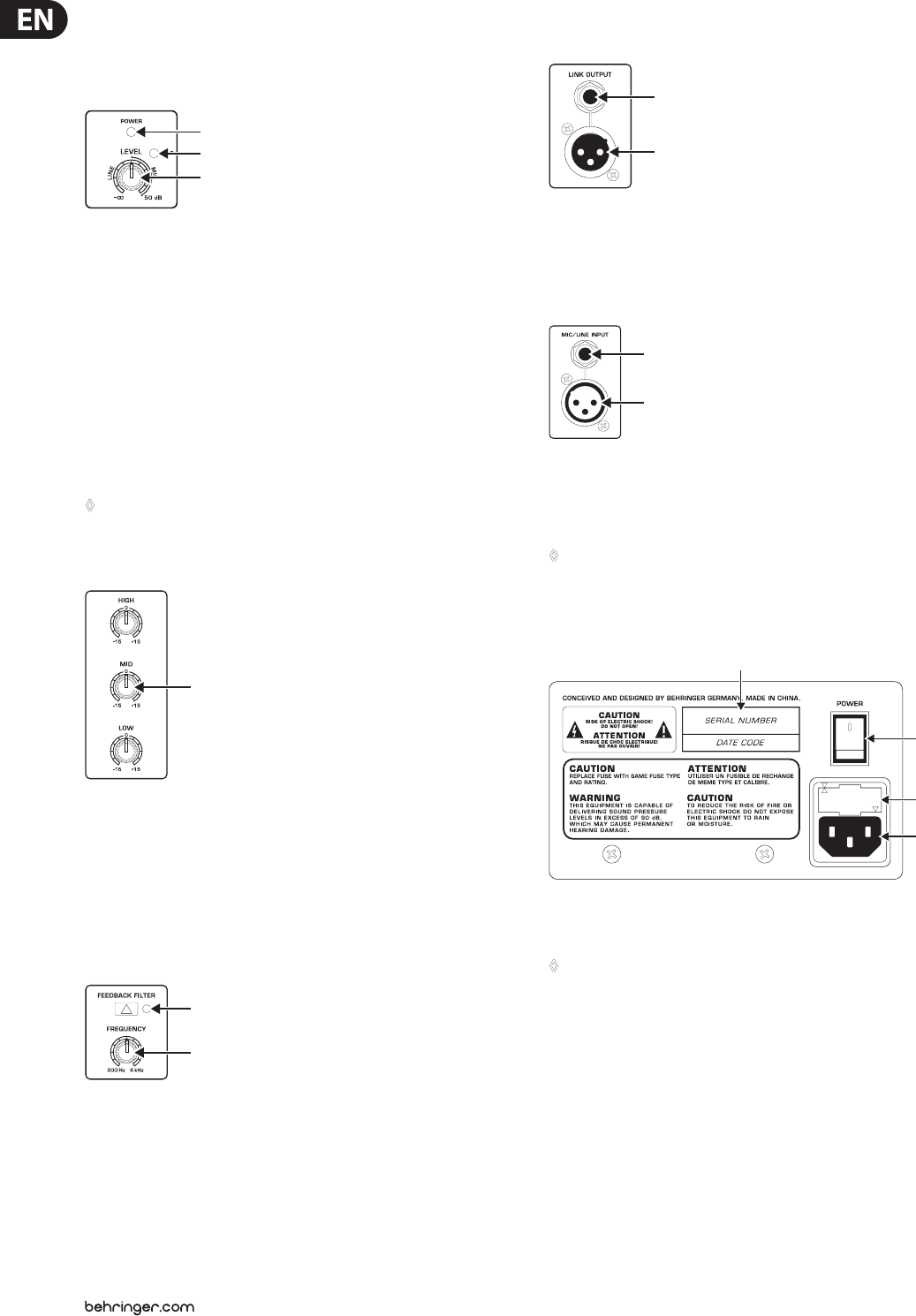
Fig. 2.4:
(7)
(8)
LINK OUTPUT
(7) + (8) The LINK OUTPUT is directly connected to the inputs of the
F1320D and carries the input signal with no processing applied. In this
way, you can route the signal to the input of another device (for example,
asecondF1320D).
Fig. 2.5:
(9)
(10)
MIC/LINE INPUT
(9) Use this ¼" stereo jack to connect a signal source that has ¼" output.
(10) Use this XLR connector to connect a signal source that has XLR output.
◊ Always use either the XLR or the 1/4" jack input, and use the LEVEL
control to adapt the input sensitivity. Never use both inputs at the
same time!
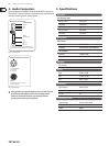
2.2 Side panel
Fig. 2.6:
(14)
(11)
(12)
(13)
Side panel F1320D
(11) Press POWER to turn on your F1320D.
◊ The POWER switch does not fully disconnect the unit from the mains.
To disconnect the unit from the mains, pull out the main cable plug
or appliance coupler. When installing the product, ensure the plug
or appliance coupler is readily operable. Unplug the power cord
completely when the unit is not used for prolonged periods of time.
(12) You can replace fuses at the FUSE SWITCH of the F1320D. Always replace
fuses with the same type. Please follow the instructions given in the
chapter“Specications.”
(13) The mains connection is established using a cable with an IEC mains
connector. This cable is delivered with the F1320D. To avoid ground-loop
hum, loudspeakers and mixing consoles should be connected to the same
powercircuit.
(14) Serial number.