


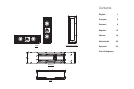
CHECK THE CONTENTS
INSTALLATION PROCEDURES
Stage 1 – cutting the sheetrock
(plasterboard)
Simple retrofitting is only possible with vertical
orientation. For horizontal orientation, follow the
instructions for new construction.
Use a stud-finding tool to find the position of the
wall studs. Preferably choose a cavity that has no
other services running through it in order to avoid
the likelihood of rattles. There should be a
minimum of 120cm (4 ft) between any cross
studs to allow sufficient working volume behind
the speaker.
Using the template provided and a spirit level,
mark and cut out the hole for the speaker.
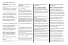
Stage 2 – preparing the cavity (Figure 6)
Pull the cable through to the top of the aperture
plus 30cm (1 ft) to facilitate connection.
Insert suitable absorbent wadding into the cavity,
but leave the area immediately behind the
aperture clear. Glass or mineral fibre normally
used for heat insulation and open cell foam are
suitable for this purpose, but ensure they comply
with the appropriate local fire and building
regulations.
Stage 3 – fitting the wall frame
Have on hand the PMK frame, the wall frame
(having removed the metal grille) and at least 2
screws from the wall frame module.
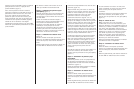
Stage 1 – fitting the PMK
Ensure the wall studding is properly prepared.
In vertical orientation, the PMK fits between two
adjacent studs on standard 40cm (16 in)
spacing. The speaker needs a minimum of 40
litres (1.4 cu ft) operating volume, so ensure there
is a minimum of 120cm (4 ft) clear height in the
cavity not obstructed by cross studs. (Figure 9)
In horizontal orientation, it is necessary to cut
through 2 vertical studs and therefore cross
studs should be fitted above and below the
speaker to support the wall. A clear vertical
spacing of 38cm (15 in) between the cross studs
is needed to provide the necessary volume for
the speaker. (Figure 10)
Keep the whole of the cavity available to the
speaker clear of services or ducting that may be
induced to rattle.
Screw the 6 brackets to the front of the PMK
frame using the self-tapping screws provided. In
vertical orientation, use the 6 anchor positions
down the long sides. (Figure 9)
In horizontal orientation, use the 4 anchor
positions along the short sides and the 2 central
ones along the long side. (Figure 10)
Screw or nail the brackets to the wall studs,
using a spirit level to ensure the frame is properly
square.
Stage 1 – fitting the back box
Ensure the wall studding is properly prepared so
that there is sufficient clearance for the back box
and its cable entry gland. The speaker baffle may
be positioned either in the centre or to one end
of the back box, allowing greater flexibility in
positioning the back box around the desired
speaker position. (Figure 16)
In vertical orientation, the back box fits between
two adjacent studs if on standard 40cm (16 in)
spacing. (Figure 13)
In horizontal orientation, it is necessary to cut
through 3 vertical studs and therefore cross
studs should be fitted above and below the back
box to support the wall. (Figure 14)
Attach the 4 brackets to the back box as
required to fix to the wall studs. Use 4 M6
machine screws and washers per bracket. If the
brackets are fitted to a short side, they overlap
and only 6 screws are required to fix 2 brackets.
Do not tighten the screws fully at this stage to
allow the brackets to slide. (Figures 13, 14 & 15)
Knock out one of the circular cable entry discs in
the back box and fit the cable entry gland. If
using vertical orientation, knock out the disc in
the short side at the open end. If using horizontal
orientation, knock out one of the discs in a long
side, preferably one nearest the open end.
Stage 1 – building in the back box
The back box is used to define the working
volume of the speaker and should be built in to
the brick or block work in a similar manner to a
window frame. The brackets, machine screws
and cable entry gland supplied will not be
required. Care must be taken to avoid the back
box rattling against the wall. It should therefore
be wedged in position such as to give a clear
gap all round. If it is desired to settle the back
box onto the lower course of bricks, use a
flexible mastic rather than cement or mortar. The
back box is not designed to take the weight of
the wall above, so a suitable lintel should be
used. (Figure 18)
Before positioning the back box in the wall,
knock out one of the circular cable entry discs in
the back box and fit the rubber grommet to
avoid chafing the cable. The cable entry gland is
not required. If the wall is an internal, single
thickness wall, it is probably easiest to use one
of the cable entries in the back face and run the
cable on the reverse side of the wall. (Figure 19)
To aid alignment, temporarily fit the front panel to
the back box the desired way round, using 2 of
the self-tapping screws. (Figure 16)
To prevent debris entering the back box, tape a
sheet of polythene or similar over the aperture
until all the brickwork is complete.
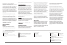
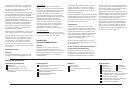
Wall frame and grille pack
Baffle assembly pack
PMK pack
Back box pack
Baffle with drivers and crossover
8x M6 x 25mm screws (baffle to frame)
Owner's Manual
M6 Allen Key
4x Card spacers
Wall frame
Metal grille with scrim attached
8x M5 x 30mm scr
ews (frame to PMK or
back box)
PMK frame
6x brackets
12x self-tap screws
Cut-out template
Back box
Foam pad
Cable entry gland
2m foam gasket strip
22x self-tap screws (front panel to back box)
16x M6 screws (brackets to back box)
16x M6 washers (brackets to back box)
M6 Allen key
Existing drywall construction (retrofit)
without back box
New drywall construction
without back box
New drywall construction
with back box
New solid wall construction
with back box
Front panel
4x brackets
Rubber grommet
2