


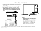
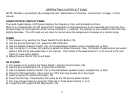
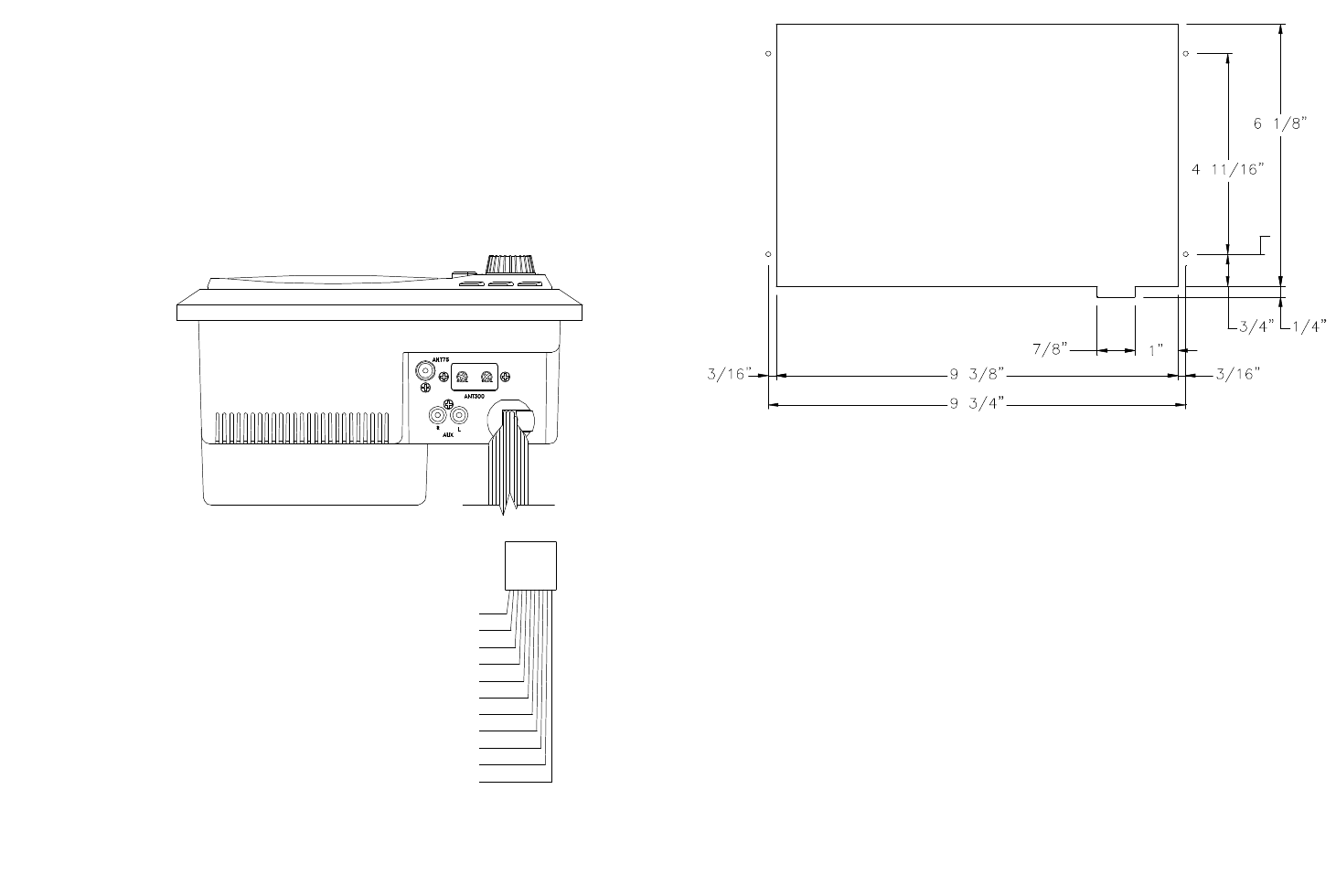
INSTALLATION AND HOOK UP
1) Cut mounting hole in desired location using mounting hole
diagram (right)
2) Route power, speaker, and antenna cables through hole,
and connect to unit as shown in hook up diagram below.
3) After making sure connections are correct, test unit
operation as described in the operation section (Do not
mount until AM antenna trimmer adjustment has been
made.
NOTES:
- Speakers must have a minimum of four Ω
impedance each.
- Either antenna may be used. Both do not
have to be hooked up at the same time.
- Do not operate this unit with only one
speaker hooked up. If a speaker fails,
replace it before operating this unit.
NOTE: Always be sure when running cables to avoid sharp edges, extreme heat sources, and any other
potential hazards.
2
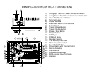
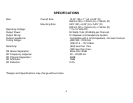
WIRING COLOR CODE
GREEN/BLACK
VIOLET/BLACK
GREEN
VIOLET
GREEN/WHITE
YELLOW
BLUE
RED
WHITE
BLACK/WHITE
ORANGE/WHITE
COLOR
TO CHASSIS GROUND
+12VDC BATTERY POWER
+12VDC IGNITION POWER
LEFT (A) SPEAKER (-)
LEFT (A) SPEAKER (+)
RIGHT (A) SPEAKER (+)
RIGHT (B) SPEAKER (-)
RIGHT (B) SPEAKER (+)
LEFT (B) SPEAKER (-)
LEFT (B) SPEAKER (+)
RIGHT (A) SPEAKER (-)
FUNCTION
FOR AWM-930