ARCHITECT
Model 960
Model 961
Installer’s Guide
™
SPEAKER HOOK-UP
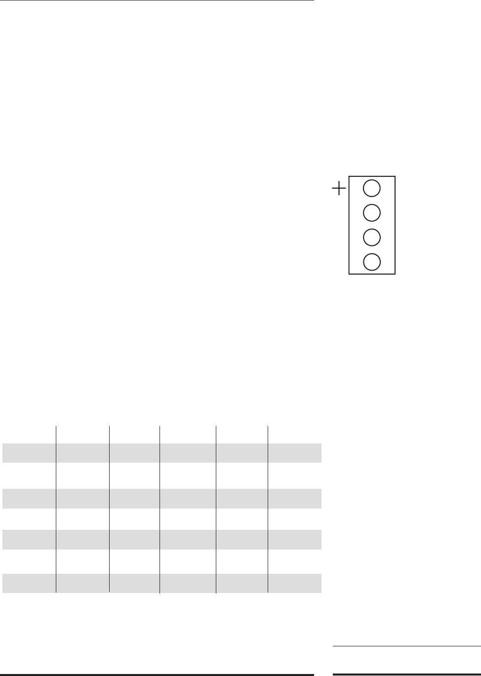
The same rule applies to the speaker wires as the RCA con-
nections. Establish a standard connection color code and stick
with it. One conductor of the speaker wire is normally marked by
a different color (silver versus copper) or there is a ribbing on one
side. Typically this marked conductor is used for the positive (+)
speaker leads. Of course the really good wire has Positive and
Negative printed right onto the wire jacket.
Your choice of speaker wire gauge and the length of the runs
also affects the speaker impedance load presented to the amplifi-
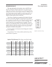
ers. As you can see in this table, even fairly short speaker runs can
have significant resistance if you use a smaller wire gauge. This
can be a benefit if you are paralleling lots of speakers. The wire
itself acts as an impedance limiter, since the amplifier cannot see a
speaker load lower than the resistance of the wire. The downside
of this resistance in the wire is that you waste some part of the
total power available to the speakers.
See the appendix for information about bridging the Architect
into mono operation.
Congratulations! You’re done with the audio hook up. Now
for the details of operation…
Speaker connection wiring
Installation:
The Long Version
25’ 50’ 100’ 250’ 500’
24 GA 1.3 Ω 2.6 Ω 5.1 Ω 12.8 Ω 25.7 Ω
22 GA 0.8 Ω 1.6 Ω 3.24 Ω 8.1 Ω 16.0 Ω
20 GA 0.5 Ω 1.0 Ω 2.0 Ω 5.0 Ω 10.1 Ω
18 GA 0.3 Ω 0.6 Ω 1.28 Ω 3.2 Ω 6.4 Ω
16 GA 0.2 Ω .4 Ω 0.8 Ω 2.0 Ω 4.0 Ω
14 GA 0.1 Ω .25 Ω 0.5 Ω 1.26 Ω 2.5 Ω
12 GA 0.08 Ω .16 Ω 0.32 Ω 0.8 Ω 1.6 Ω
13
Speaker Wire Resistance Wire Gauge versus Run Length


