


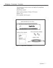
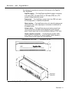
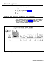
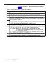
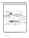
The following items describe all control and indicator functions illustrated in
figure 2-1:
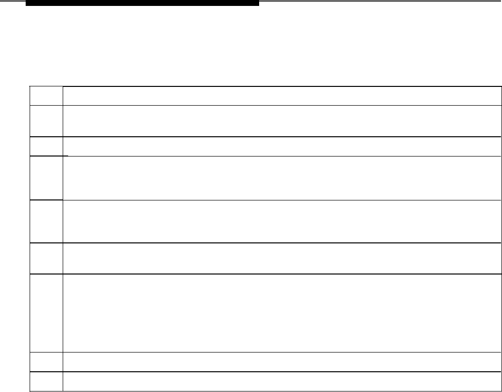
Table 2-1. Controls and Indicators, Terminals and Connectors
1.
2.
3.
4.
5.
6.
7.
8.
9.
AC Power in: 100-250VAC, 50/60 Hz, 1 amp (AmpliCenter is self-switching.)
0dBm out, an auxiliary output that differs from the main 70.7V output in that it is a low level
(0dB), 600 ohm balanced output used for driving a remote or off-premises amplifier
DC Power, and 70V audio out to Controller
Bass control screw-type adjustment pot. Attenuates low frequencies so that horns and small
speakers are not overdriven by excessive bass energy. Cut-off frequency is adjustable from 50
Hz (full CCU) to 400 Hz (full CU)
Music In: left and/or right channels with ground;
Paging In: redundant paging input (ground, C1, tip, and ring)
70V Out: Balanced output used for terminating the loudspeaker wiring
Screw-type pots: VOX sensitivity level, Music ducking (mute level for music during voice
page), Music level for various music sources
LEDs: green - power on, lights when AC line voltage is applied to AmpliCenter
red – overload, lights when the AmpliCenter output exceeds its output power rating.
This can occur when total speaker load is greater than the output rating, or
when speaker wiring is shorted
red - unbalanced output, indicates when one speaker lead is accidentally shorted to ground
green – page accessed, lights when voice paging is active
Telephone system mode switch: dry loop 600 ohms, dry loop Hi Z, ground start, and loop start
From host telephone system or Controller RJ11 connector paging audio and control
2-4 Hardware Configuration