AtlasSound.com
1/5
1601 JACK MCKAY BLVD. ENNIS, TEXAS 75119 U.S.A.
TELEPHONE: (800) 876-3333
FAX (800) 765-3435
©2008 Atlas Sound L.P. All rights reserved. Atlas Sound and Strategy Series are trademarks of Atlas Sound L.P. All other trademarks are property of their respective owners. ATS001619 RevB 10/08
Strategy Series
®
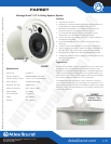
II 8" In-Ceiling Speaker System
FAP82T
Specifications
Woofer Size 8" (203mm)
Woofer Impedance 8Ω Direct Coupled (Nominal)
Transformer Taps at 70.7V 1.9, 3.8, 7.5, 15, 30, & 60 Watts
Power Handling 70 Watts RMS (at 8Ω)
Sensitivity (1W / 1M) 90dB Average
Frequency Response 65Hz – 20kHz (±5dB)
Magnet Weight 21oz (580g)
Cut-Out Diameter 14" (356mm)
Height 12
3
⁄4" (324mm)
Diameter 15
3
⁄4" (400mm)
Features
• Highefficiency8"driver
• ExtendedLowFrequencyResponsefromtheOptimallyTunedand
PortedDeepDrawnGalvanizedSteelEnclosure(937in
3
)
• 60WattsEnhancedQuality70.7V/100VInternalTransformer
MinimizesInsertionLossandMaintainsLowFrequency
• FrontMountedTapSelectorSwitchforEasySystemTuning
Adjustments (1.9 – 60 watts @ 70.7V Plus 8Ω Bypass)
• Unique“TrapDoor"InputSectionAllowsforThroughConduitRuns
withRigidorFlexConduit
• 4PoleDetachablePhoenix/EuroStyleConnectorAllowsEasy
Pre-wiring
• “Press-Fit"GrilletoBetterBlendintoContemporaryArchitecture
• ShipsCompletewithSpeaker/TransformerFactoryAssembledinto
BackCan,Grille,andUniqueC-Ring/V-RailMountingHardware
• MaybePendulumMountedviaTopMountedEyebolt(Included)
• EnclosureisFinishedinWhiteforOptimumAestheticswhenHungin
Open Ceiling Applications
• UL1480Listed
Applications
The Atlas Sound FAP82T is a premium performance 70.7V / 100V tuned
&ported8"coaxialceilingspeakersystemperfectlysuitedformany
businessmusicandpublicaddressapplications–especiallyapplications
where high ceilings require loudspeakers with increased efficiency and
tighterpatterncontrol.The8"coaxialspeakersystemfeaturesextended
lowfrequencyresponserivalingthatofmanysubwoofers.
The FAP82T will satisfy the needs of owners, architects, contractors,
andconsultantsbydeliveringtrue,highfidelitysoundreproductioninan
attractive and easy-to-install system. The FAP82T is ideal for high intelligi-
bilityvoice,music,andsignalreproductionincommercial,industrial,and
institutional applications.
FAP82T
FAP82T
(Pendulum Eyebolt &
Phoenix / Euro
Style Connector)
MITEK CORP. © 2008
(preliminary)