


Specifications subject to change without notice
© 2001 Atlas Sound LP Printed in U.S.A. 000501 SL1-1512
1601 JACK MCKAY BLVD. / ENNIS, TEXAS 75119 U.S.A. / TELEPHONE: (800) 876-3333 / FAX (800) 765-3435
STRATEGY SERIES
™
4" SYSTEM INSTALLATION
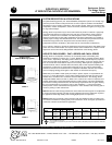
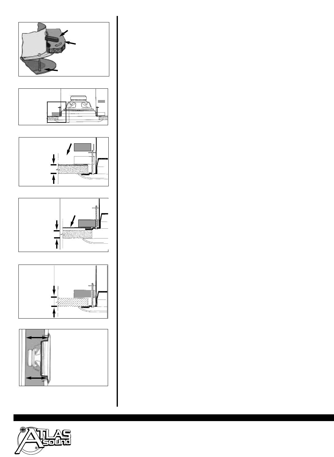
Figure 1: Enclosures mount quickly using rotating clamps. Grille push-mounts with “easy-fit”
welded studs.
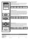
Figure 2: Enclosure installation from below ceiling using tile bridge above. This room-side in-
stallation into suspended tile utilizes rotating clamps to sandwich tile between bridge and
enclosure. Max. ceiling thickness is 1
1
⁄4".
Figure 3: Enclosure installation from above ceiling using tile bridge (new construction).
Rotating clamps are used to pre-mount tile bridge to enclosure, allowing system to be posi-
tioned in ceiling before tiles are set. Please note maximum ceiling thickness in this application
is
5
⁄8" to allow grille studs to mount into enclosure.
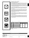
Figure 4: Enclosure installation from below ceiling without tile bridge. This blind-mount instal-
lation method, which is most common in plaster, drywall and retrofit applications, is accom-
plished by cutting an opening to size, inserting the enclosure and rotating the clamps. Max.
ceiling thickness is 1
1
⁄4".
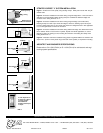
Figure 5: Illustrates wall-mount installation using plaster ring Model FAPR-4. A minimum wall
depth of 2
7
⁄16" (from rim of the plaster ring to the back of the speaker) is required for mounting.
ARCHITECT AND ENGINEER SPECIFICATIONS
Please refer to SL1-1533 (FA134) or SL1-1524 (FA114) for architectural and engi-
neering system specifications.
FIG. 1
FIG. 2
FIG. 3
FIG. 4
FIG. 5
Ceiling
Welded Stud for
Pre-Mount Installation
Rotating Clamp
Area of detail for Figures 2, 3 & 4
Tile Bridge
Tile Bridge
2
7
⁄16" Min. Depth from rim
of plaster ring to back of
4" Strategy speaker.
Note:Transformer
equipped models require
4
3
⁄8" depth.
Max. thickness
of 1
1
⁄
4
"
Max. thickness
of 1
1
⁄
4
"
Max. thickness
of
5
⁄
8
"