


4
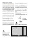
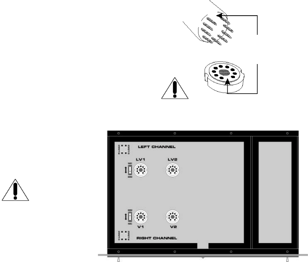
Figure 3 - Tube pin alignment with the socket.
WARNING - DISCONNECT the AC Detachable Power Cord from
the SFP-1 and wait 5 minutes b e f o r e removing the chassis cover.
Note the larger space
between two of the pins and
holes for proper alignment
of tube and socket.
INSERTION OF THE TUBES AND G A I N S E T T I N G
The SFP-1 comes with two Sovtek 6922 (6DJ8-type) and two 12AT7A
tubes (the SFP-1 Signature comes with two Mullard 6DJ8/6922 and
two Gold Aero12AT7A Gold Grade), individually boxed, marked
and bagged along with a cotton glove, screwdriver, and screws for
fastening the SFP-1 cover. The following tube types will work under the
same technical parameters as the 6922 and require no circuitry modi-
fication to function:
• 7308/E188CC • 6DJ8/ECC88 • E88CC •12AT7A/E C C8 1
Please read and follow these instructions carefully for initial tube inser-
tion or tube replacement. Great care was taken in the testing, selection
and matching of the supplied tubes in order to ensure proper opera-
tion of the unit. Casual replacement of tubes is NOT recommended.
1. Be sure that the AC DETACHABLE POWER CORD IS DISCON-
N E C T E D from the SFP-1 for 5 minutes prior to removing the chassis
cover in order to allow internal voltages to drain.
2. Using the Phillips screwdriver, remove the cover of the SFP-1. For
convenience, only two of the screws are fastened.
3. When handling the tubes, it is recommended that the cotton gloves
provided be worn to prevent skin oils from depositing on the glass sur-
face and possibly causing the tube to become prematurely “gassy”,
thereby shortening the tube’s useful operating life.
4. Inspect the tubes for code markings. They will be coded individually,
each with one of the following codes: LV1, LV2, V1 and V2.
5 . Inspect the tube sockets in the SFP-1 Phono Stage for the codes
matching the codes on the tubes. The coding is printed on the PCB cir-
cuit board beside the tube sockets. See Figure 2 for further clarification.
6 . Take the tube marked LV1 and inspect the pins, noting the larger
space between two of the pins. This space will align with the same
larger space between two of the pin holes on the socket. Insert the LV1
tube into the LV1 tube socket, making sure all pins and pin holes are
aligned (see Figure 3). Do not force the tube into the socket. “Rock” the
tube gently while pushing slowly until the tube is firmly seated.
Repeat this step for the remaining tubes; LV2 tube to the LV2 tube sock-
et, V1 tube to the V1 tube socket and V2 tube to the V2 tube socket.
7. Two slide switches for gain setting left and right channel are locat-
ed beside the LV1 and V2 tube sockets. These switches are to be
moved inward to the MM position if a Moving Magnet or high out-
put cartridge of 1.0mv or greater is in use. If a Moving Coil or low to
medium output cartridge of 0.2mv to 1.0mv is used, slide the switch-
es outward to the MC position (see Figure 2).
N O T E : If insufficient gain is realized from the SFP-1 with a high output
cartridge when in the Moving Magnet mode, an extra 20 dB of gain
may be utilized by the Moving Coil mode. The SFP-1 has sufficient
overload reserve to handle high signal input levels if this mode is
chosen.
Also refer to the Operation section of this manual for turntable set up
if a Moving Coil mode is chosen.
8. Replace the cover and fasten it with the screws provided. The SFP-1
Phono Stage is now ready for operation.
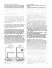
Figure 2 - Overview of the SFP-1
Phono Stage showing tube placement,
MM/MC slide switches, R-Load and
C-Load locations.
WARNING - DISCONNECT the AC
Detachable Power Cord from the SFP-1
and wait 5 minutes b e f o r e removing the
chassis cover.