


2
1. Lay the case down, with the top open.
2. Make sure you have the correct I/O panel for your motherboard. If the panel
provided with the case isn’t suitable, please contact your motherboard
manufacturer for the correct I/O panel.
3. Line up your motherboard with the standoff holes, and remember which holes
are lined up. Not all motherboards will match with all the provided holes;
this is normal and won’t affect functionality.
4. Remove your motherboard by lifting it up.
5. Screw the brass standoffs into the threaded holes that line up with your
motherboard. Do not over-tighten the standoffs. Some standoffs may be
pre-installed for your convenience.
6. Place your motherboard on the brass standoffs.
7. Secure your motherboard to the standoffs with the provided Philips-head
screws. Your motherboard is now installed.
Connecting the Switches and LED
1. Connect the Reset switch (labeled RESET SW) to the motherboard at the RST
connector. Polarity (positive and negative) does not matter for switches.
2. Connect the Power Switch (labeled POWER SW) from the front LCD display
to the PWR connector on the motherboard.
Note: The Power Switch from the front I/O is connected to the LCD display
module by default. This will allow you to turn your system on and off using
the remote control. If you choose to connect the Power Switch from the front
I/O directly to the motherboard instead of via the LCD display, you won’t be
able to control system power using the remote control.
3. The Power LED (labeled POWER LED) connector is located behind the Reset
connector. For LEDs, colored wires are positive (+). White or black wires are
negative (–). If the LED does not light up when the system is powered on, try
reversing the connection. For more info on connecting LEDs to your mother-
board, see your motherboard manual.
4. The Hard Drive LED (labeled HDD LED) connects to the hard drive activity
header on your motherboard or RAID card.
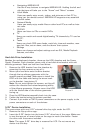
Installing the Power Supply
1. Orient the power supply vertically, and set it on the three rubber pads at the
bottom of the PSU chamber.
Note: Power supplies with fans on the bottom of the power supply will need
to be mounted so that the fan is facing the side ventilation port. The power
supply mounting holes on your Fusion Remote Max case allow the PSU to be
installed in either orientation.
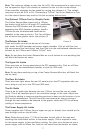
2. Push the power supply to the back of the case and align the mounting holes.
3. Secure the power supply to the case with the screws provided.
4. Loosen the screw on the sliding black plate and widen the opening so you can
feed the necessary power cables through to the other side.
5. Slide the plate back to constrict the opening and secure it with the screw,
so that the airflow in the case works as designed.
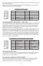
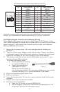
Connecting the USB Ports
You will find a single 10-pin connector on a cable attached to the front USB ports.
This is an Intel® standard connector that is keyed so that it can’t be accidentally
reversed when connected to a proper Intel® standard motherboard header. Connect