


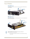
Tuner Modules
42
Tango / Mi-Series Audio Controllers
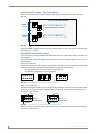
Audio Controller Jumpers - Dual Tuner Setting
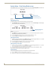
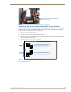
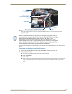
If two tuner modules are to be used, the Audio Controller jumpers should all be set to ON, as shown in
FIG. 60:
Move the TUNER 2 jumpers to the ON position by connecting the top 2 sets of pins (pins 3-2) and leaving the
bottom pins (pin 1) exposed.
DAS-AMFM Tuner Module Jumpers
There are jumpers on the DAS-AMFM Tuner Module that must be set to differentiate Tuner 1 from Tuner 2 in
the Controller.
The instructions for setting these jumpers differ based on the color of the “Interface Board” (red or green), as
described below:
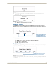
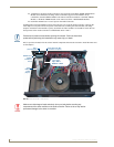
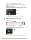
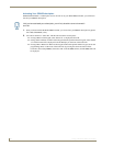
Red Interface Boards
Examine the configuration of the jumpers located on the Tuner Modules, to the right of the 20-pin ribbon cable
connector (as seen when viewing the installed modules from the front of the controller).
Note that there are two rows of 5 pins as shown in FIG. 61.
With only a single tuner, all pins are jumpered.
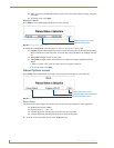
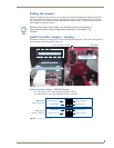
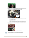
Green Interface Boards
Examine the configuration of the jumpers located on the Tuner Modules, to the right of the 20-pin ribbon cable
connector (as seen when viewing the installed modules from the front of the controller). Note that there are
two rows of 5 pins (FIG. 62).
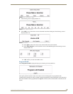
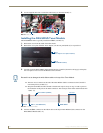
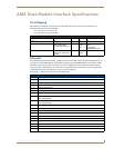
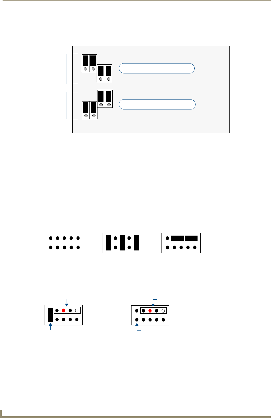
Remove all jumpers from the new tuner, and attach the 2-wire (red and white) end of the cable included with
your kit to the pins (FIG. 63):
FIG. 60 Audio Controller Jumper Configuration (Dual Tuners)
FIG. 61 Tuner Module Jumper Configuration (Red Interface Boards)
FIG. 62 Tuner Module Jumper Configuration (Green Interface Boards)
Tuner 1 jumpers (in ON position)
Tuner 2 jumpers (in ON position)
Top Left of Rear-Board Pin Bus
3
1
3
1
3
1
3
1
TUNER 1
Jumpers
TUNER 2
Jumpers
(no jumpers)
Dual Tuners: TUNER 1
Dual Tuners: TUNER 2
Tuner 1
Jumper
Cable
Configuration
Tuner 2
No Jumper
Cable
Configuration