


Installation Guide
DAS-AMFM AM/FM Tuner Module
Overview
Add AM/FM Radio functionality to your Mi Series system with the
DAS-AMFM AM/FM Tuner Module (FG1110-01).
• Up to two DAS-AMFM modules can be added to each Mi Series
controller.
• Each tuner module uses one source input on the audio controller.
WARNING: Disconnect all power sources before opening the chassis. Fail-
ure to disconnect power before performing this installation may cause injury
or death.
CAUTION: Make sure to discharge all static electricity from your body
before touching any components of the tuner modules or the audio control-
ler. Failure to do so may lead to permanent damage to the tuner or
controller.
Single Tuner Installation Instructions
Installing The Tuner Module in the Controller
1. Remove the cover from the controller.
2. With the back of the unit facing you, remove the screws from the
Tuner Option cover plate at the right top corner of the rear panel
(FIG. 1) and remove the plate. Retain the screws, as they will be used
to install the tuner.
3. Carefully insert the DAS-AMFM tuner module into the controller, with
the electronics facing up, and use the screws that attached the Tuner
Option cover plate to secure the tuner to the controller.
Note: Be careful not to damage the white ribbon cable on the top of
the Tuner module.
4. Place the Rear Panel connector at the end of the ribbon cable (FIG. 2)
on the rear board pin-bus, keeping the red stripe at the top.
5. Connect the "Tuner 1" connector on the ribbon cable to the Tuner 1
module (FIG. 3).
Note: The ribbon cable must be oriented so that the red stripe is con-
nected to Pin 1 on the connector.
• Be sure that both ends of the cable are securely plugged into their
respective boards through the 20-pin connectors (FIG. 4).
Setting the Jumpers in the Controller
Examine the configuration of the jumpers on the left end of the rear board,
as seen when viewing the rear board from the front of the controller.
The jumpers should be in the “Off” position, with the top pair of pins in each
configuration exposed and the jumpers connecting the second and third set
of pins.
Move the top set of jumpers to the “On” position, connecting the first two
sets of pins and leaving the third set exposed (FIG. 5).
• Reconnect power to the unit and turn it on to make sure that the tuner
is properly integrated with the controller.
• If the tuner is functioning properly, remove power and replace the unit
cover.
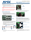
FIG. 1 Rear Panel Tuner with Tuner Option cover plate
FIG. 2 Tuner Ribbon Cable
Tuner 1 (installed)
Tuner Option
cover plate
Tuner 2
Tuner 1 Rear Panel
RED STRIPE (to Pin 1)
not used
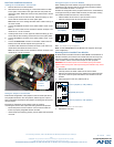
FIG. 3 Tuner 1 Module Connection
FIG. 4 20-Pin Connector and Ribbon Cable
FIG. 5 Controller Jumper Configuration
Tuner 1 Connector
Rear of controller
Tuner 1 jumpers (in “On” position)
Tuner 2 jumpers (in “Off” position)
Exposed pair of pins