


Installation Guide
AXR-RF RF Receiver
Overview
The AXR-RF Radio Receiver provides wireless reception of AMX radio
frequency (RF) transmitters. The AXR-RF connects to an Axcess Central
Controller with an AXlink, 4-pin captive-wire connector. When required for
large areas, or multiple-room coverage, multiple receivers can be
connected in parallel on the AXlink bus.
Installation
Configuring the AXR-RF
Use the eight-position DIP switch on, the rear of the AXR-RF, to set the
device number. A device number is assigned to devices connected to the
AXlink bus. Every device on the bus must have a unique device code. The
device number must match the device assignment in the Axcess program.
AMX assigns device numbers in three groups:
• Axcess Control Cards: 1 - 95
• Axcess Bus Boxes: 96 - 127
• Axcess Panels/Receivers: 128 - 255
Setting the DIP Switch
Locate the device DIP switch on the rear panel of the AXR-RF and set it to
the desired binary device number. The device number is set by the total
value of DIP switch positions that are ON (down).
NOTE: If you change the device number, remove and reconnect the AXlink
connector. This enters the new device number into memory.
Although the AXR-RF is a bus device, it should be numbered in the 128-255
range, because it is a receiver.
Setting the RF Validation Level
An RF transmitter must send repetitions of data for the receiver to accept it
as valid data. In some installations, interference and physical structures
may interfere with the receiver's ability to detect the transmitted signal. The
signal may become distorted. The receiver can be set to use either two or
three repetitions of sequential signals to validate and accept the signal
data. To set the receiver's RF level.
1. Locate jumper pins labeled P3 on the circuit board.
2. Position the P3 RF validation jumper to select the number of valid RF
data repetitions to be accepted, as shown in FIG. 2:
Wiring Guidelines
The AXR-RF requires regulated ±12 VDC power to operate properly. The
Central Controller supplies power via the AXlink cable. The maximum
wiring distance between the Central Controller and AXR-RF is determined
by power consumption, supplied voltage, and the wire gauge used for the
cable. The table below lists wire sizes and maximum lengths allowable
between the AXR-RF and Central Controller. The maximum wiring lengths
for using AXlink power are based on a minimum of ±13.5 VDC (no load
voltage), available at the Central Controller's power supply.
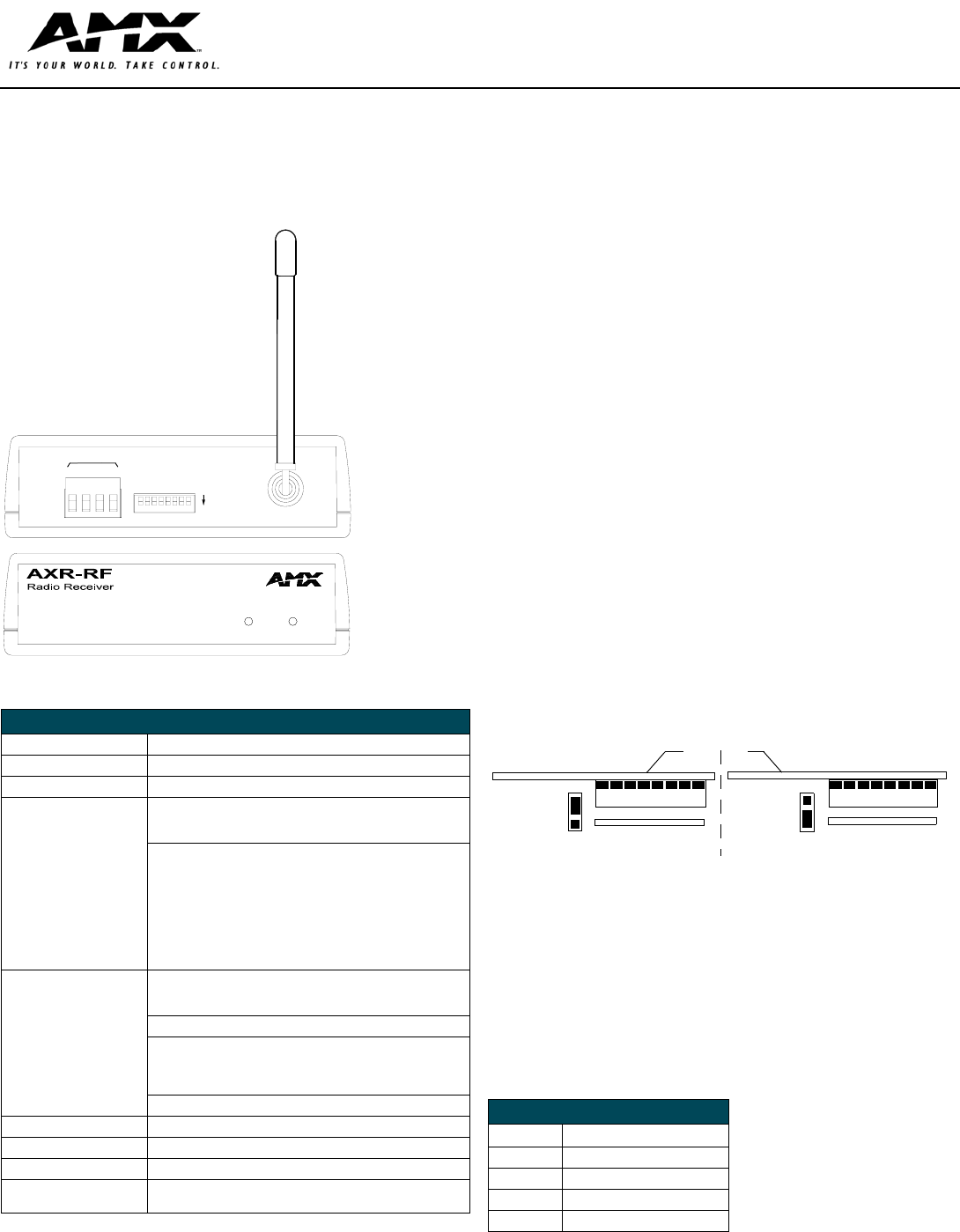
FIG. 1
AXR-RF RF Receiver
Specifications
Power Consumption 780 mW; ±12 VDC, 65 mA (max.)
Dimensions (HWD) 1.5" x 5.09" x 5.27" (3.81 cm x 12.93 cm x 13.39 cm)
Weight 10.56 oz. (299.37 g)
Front Panel Components:
Radio data LED
Red LED lights to indicate the AXR-RF has received an RF signal
from an AMX transmitter.
AXlink LED Green LED that lights to indicate AXlink power/data status as fol-
lows:
• One blink/second indicates power is active and AXlink
communication is working.
• Two blinks/second indicates the devices specified in the main
program do not match the devices found.
• Three blinks/second indicates there is an AXlink communication
error
• Full on indicates there is either no AXlink control/activity (but the
power is On) or the Axcess program is not loaded.
Rear Panel Components:
AXlink connector
4-wire captive-wire AXlink connector for the Central Controller pro-
vides data and nominal ±12 VDC power.
Device number DIP Switch 8-position DIP switch sets the device number for the AXR-RF.
RF antenna Receiving antenna screws into the TXC antenna connector. If it is
necessary to place the antenna in a remote position, use up to 6 ft.
(2 m.) of RG-174 coax cable as an extension. Extend the antenna
vertically during use.
TXC antenna connector Antenna coaxial connector
Receive Frequency 418 MHz standard (other frequencies are available)
Maximum Range 300 feet (91.44 m)
Enclosure Molded black matte plastic
Options • Alternate frequencies available
• PS2.8 Power Supply
AXP
PWR
AXM
GND
DEVICE
AXlink
ON
DATA
RADIO
AXlink
rear
front
FIG. 2 RF validation jumper settings
Wiring Specifications
Wire size Maximum wiring length
18 AWG 1805.7 feet (550.37 m)
20 AWG 1142.4 feet (348.20 m)
22 AWG 712.2 feet (217.07 m)
24 AWG 448.9 feet (136.82 m)
P3
P3
Setting for 3 validations Setting for 2 validations
Rear panel
DIP Switch
DIP Switch