


4081 User Manual Issue 2
(these subsequent units should have the blue USB/RS485 button on the
rear pushed out to select RS485 control).
The RS 485 communication protocol uses standard RJ9 connectors for
connecting cables where multiple units can be chained together (cabling
not supplied).
Please note that when connecting multiple units, each 4081 should have a
unique ID as described below.
Cable Specification
The RS-422 specification recommends 24AWG twisted pair cable with a
shunt capacitance of 16 pF per foot and 100 ohm characteristic
impedance.
These recommendations should be used for RS-485 systems as well.
We also recommend using shielded cable.
There are many cables available meeting the recommendations of RS-485
made specifically for this application. Another choice is the same cable
commonly used in the twisted pair Ethernet cabling. This cable, commonly
referred to as Category 5 cable, is defined by the EIA/TIA/ANSI 568
specification.
This cable has a maximum capacitance of 17 pF/ft (14.5 pF typical) and
characteristic impedance of 100 ohms.
Category 5 cable is available as shielded twisted pair (STP) as well as
unshielded twisted pair (UTP) and generally exceeds the recommendations
for RS-422 making it an excellent choice for RS-422 and RS-485 systems.
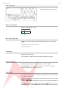
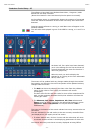
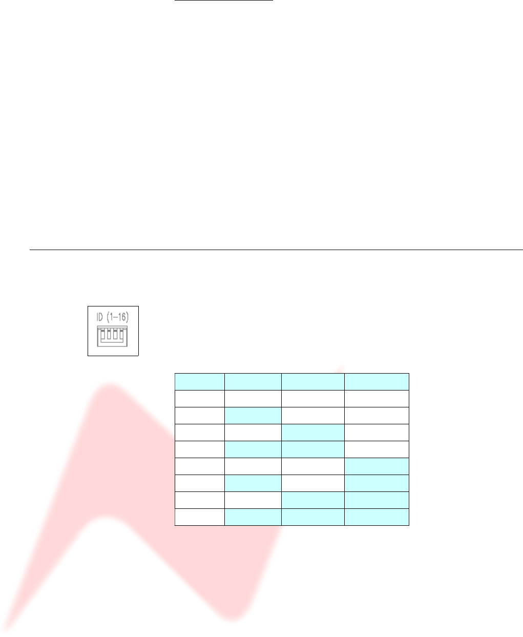
4081 unit ID dip switches
When remotely controlling more than one unit, the ID dip-switches on the
rear of the unit need to be set so that each sequentially numbered unit on
the chain responds to the correct commands.
The first 3 switches from left to right are used to set the machine IDs from
1-8. These switches are On when in the down position (the right-most
switch on this block – Switch 4 - puts the unit into 'Bootloader Mode'
where the unit software can be updated via USB, so is therefore not used
to set the unit ID).
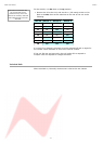
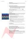
Unit ID Switch 1 Switch 2 Switch 3
1 Off Off Off
2 On Off Off
3 Off On Off
4 On On Off
5 Off Off On
6 On Off On
7 Off On On
8 On On On
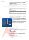
Where there are more than 8 units on an RS 485 chain, the IDs for units
greater than 8 are set using a dip-switch on the switch-block labelled
SW2 inside the unit (just next to a programming connector labelled J14
on the middle left of the board).
- 7 -