


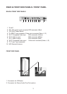
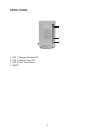
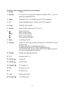
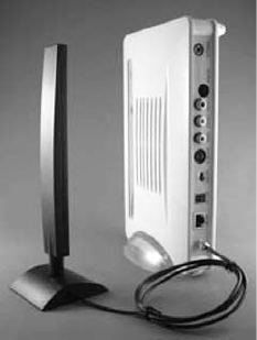
FREAR SIDE PANEL
1. RJ-45
2. "DC 12V" power input connector
3. "OFF / ON" Power Switch
4. "S VIDEO" input connector
5. "AV1" Composite Video input RCA
connector (Yellow)
6. "AV1" Audio L input RCA connector
(White)
7. "AV1" Audio R input RCA connector
(Red)
8. "AV2" Composite Video input
3.5mm mini connector (Video, L, R)
9. "TV Tuner" input connector
10.WiFi External Antenna
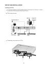
The RJ45 is for updating firmware of
TR1a or hooking TR1a to Ethernet
Network for linking TR1a to all other
equipment with IP addresses linked to the
Ethernet Network.
This DC 12V power input connector is for
connecting 12VDC power from TR1a
Power Adaptor to the TR1a.
Slide the switch to left hand side will turn
the power of TR1a OFF. Slide the switch
to right hand side will turn the power if the
TR1a ON.
This is an input connector for "S VIDEO"
sources.
This is Composite Video input RCA
connector (Yellow) for AV1 for hooking to
Composite Sources.
This is Audio L input RCA connector
(White) for AV1 for hooking to Composite
Sources.
This is Audio R input RCA connector
(Red) for AV1 for hooking to Composite
Sources.
This is a 3.5mm mini connector with
Video, L, R for Composite Video "AV2"
input for hooking to Composite Sources.
This is a connector for hooking to TV
Antenna or Cable TV's.
This connector is for hooking to external
5GHz 802.11a WiFi Antenna.
5