


Page 7 of 21 www.alfaradio.ca AlfaSpid Rotator
Alfa Radio Ltd. 11211 - 154 St. Edmonton, Alberta, Canada T5M 1X8
Bench Testing of Control Box
The control box is normally expected to be operated from a 12 Volt
DC supply; however it may be operated from other unregulated DC or
AC sources as well. DC or AC voltage levels between 10 and 26
Volts capable of at least 5 Amps are acceptable, typically 12 or 14
Volts.
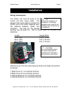
The polarity of the power to the control box input leads is not critical
for D.C. operation; a diode rectifier on the input will provide the proper
polarity to the electronics and provide reverse polarity protection as
well as A.C. operation.
TIP: Because of several steering diodes in the motor path, the
voltage delivered to the motor (neglecting wire loss) will be about 1.4
volts less than the power supply voltage. For longer runs and/or
thin wiring a higher voltage (up to approx 24V) to the control unit is
beneficial. A simple way to estimate if the voltage to the motor is
adequate is by timing the rotation. Under no or a very small load, the
360 degree rotation time with 12V DC at the motor is about 120
second (2 minutes). With 24 V DC is about 60 second (1 minute). A
DC Ammeter in the motor lead is also useful, it should indicate
between 1 and 3 amps with a small load. On windy days or heavy
load, the current may fluctuate up to 3 to 5 amps.
Notes – testing and troubleshooting
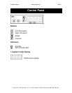
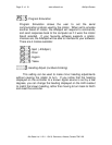
Pressing
should make the rotator move clockwise. Pressing
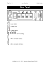
should make the rotator move counter-clockwise. If rotation is
reversed, switch lines 1 and 2 on the back of the controller.
Impulse sense lines (3 & 4) have no polarity concerns.
Part of the protection circuitry involves removing motor power if
the controller receives no sense indication. If the motor turns for
a few seconds and then you hear the relay in the control box drop
out, the motor has either stalled or there is a problem in the impulse
sense wiring.
It is highly recommended to ground the Control Box.